Data Structure - souliss/souliss GitHub Wiki
Introduction
Souliss Data Structure is an arrangement of the information defined into the node and exchanged over MaCaco protocol, that drives the communication between different nodes and user interfaces. A value into a Data Structure assumes a different meaning depending on its position in the structure, giving a common interpretation to all other devices that has access to that data. MaCaco defines both an event-based communication and a data structure, this let all Souliss enabled devices to share their data and give a consistent interpretation of such information.
Data Structure Area
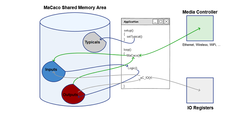
The data structure (also called MaCaco Shared Memory Area) from the user point of view is split in three sub-areas:
- TYPICALs LOGIC (in short TYPICAL) : It's a logic or a functionality that is standard for a generic type of device, representing a physical appliance (ie. sensors, lights, or a gate motor, etc.). It is addressed with an unique identification number. These identification numbers and the logic associated to a Typical are not defined in MaCaco, but at the application level. In the Data Structure an area for holding the defined Typicals is allocated.
If you are familiar with other automation protocols, the TYPICAL match the Zigbee profiles or the openHAB items.
-
INPUT : It's the area of the Data Structure holding incoming information from other nodes or application within the same node. Data included in the inputs are processed at the application level with API calls.
-
OUTPUT : It's the area of the Data Structure containing output information to other nodes or application within the same node, output data are inserted and handled at application level.
-
SLOT : A slot is a partition of the Data Structure, each sub-area (Typical, Input, Output) is split in SLOTs. At the application level slots are assigned to logics or functionality, mapping devices to each one of these slots. Complex typicals (like air-conditioners and RGB lights) require more than one SLOT.
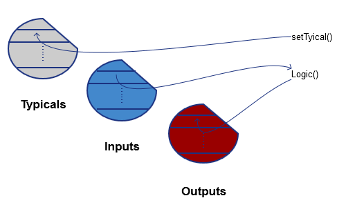
Previous diagrams shows the structure of the MaCaco Shared Memory Area and its interaction at the application level. The TYPICALs are defined by the application during setup() call, this declares which devices are located on that node at which position (SLOT). During sketch loop() main function, the INPUTs are written by the communication protocol (or the local IOs), are then processed by the logics, and the result is finally stored into the OUTPUT slots. Those are available through the communication protocol to any other node in the network.
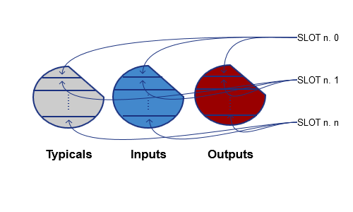
Each device is assigned to a SLOT, so that a portion of the memory area (the same one) is assigned to all three sub-areas. So, if we write a command in the INPUT of SLOT number 0, the result will be written in the OUTPUT area of the same slot number. The identification of the object type is done via the same slot number in TYPICAL memory area.
A simple example
Suppose to setup a node with a single lamp you want to control. At first, setup() function is used to insert the TYPICAL with its unique number (0x11) that identifies the object lamp; each lamp is then assigned to a SLOT in order to have an its own area of the memory for IN and OUT data.
#define SLOT_ LIGHT1	0
#define SLOT_ LIGHT2	1

// Set the typical logic to use, T11 is a ON/OFF Digital Output with Timer Option

Set_T11(SLOT_LIGHT1);
Set_T11(SLOT_LIGHT2);
Writing a command in the INPUT assigned for that lamp will result in a command, no matter from where this is coming. The code below attaches hardware PIN 2 and 3 to relevant slots, so that inputs on those pins are translated to toggle (ON / OFF) commands:
// Use Pin2 as ON/OFF command for first light
DigIn(2, Souliss_T1n_ToogleCmd, SLOT_LIGHT1);

// Use Pin3 as ON/OFF command for second light
DigIn(3, Souliss_T1n_ToogleCmd, SLOT_LIGHT2);
An external node can force inputs using the communication protocol, if on another node is used a RemoteInput() command, that node will control the lights.
RemoteInput(network_address_1, SLOT_LIGHT1, Souliss_T1n_ToogleCmd);
To execute the input command is used a logic, that is included in the Souliss APIs
// Execute the logic
Logic_T11(SLOT_LIGHT1);
Logic_T11(SLOT_LIGHT2);
To have effect the OUTPUT shall be attached to an IO of the board, so that the actual state of the light is translated to real commands to lamps as objects. In this case they are mapped to PIN 8 and 9.
// Use Pin8 as output on the electrical load
DigOut(8, Souliss_T1n_Coil,LIGHT1_NODE1);

// Use Pin9 as output on the electrical load
DigOut(9, Souliss_T1n_Coil, LIGHT2_NODE1);
User Interfaces
The user interfaces read once the TYPICALs defined into the nodes, in this way is known for each node the available functionality (light, door and others) and this allow to build a list of devices and properties without additional configuration effort.
Once that is known the TYPICAL the user interface expose to the user only the available commands and shows the relevant feedback states from the node.