Adding a Battery and charging module - sorinbotirla/esp32-marauder-ESP32-3248S035C GitHub Wiki
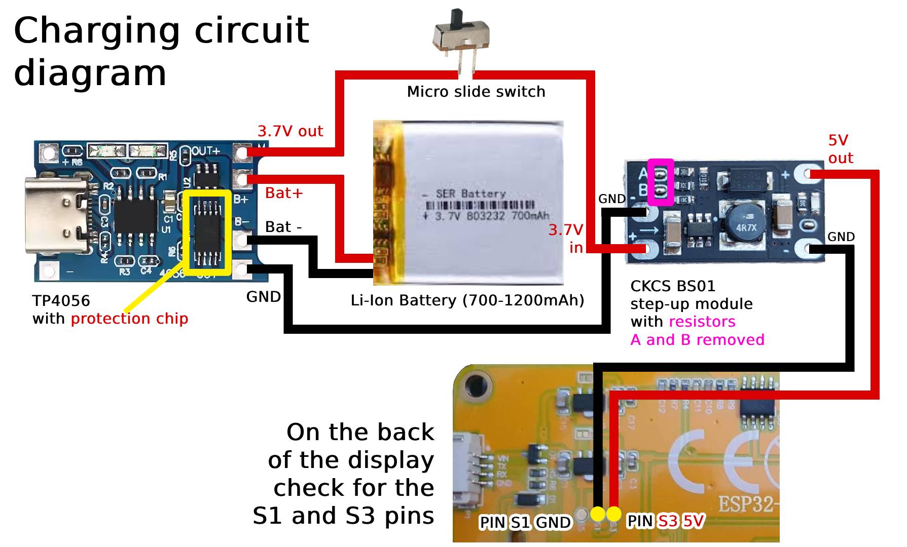
I have used a 3.7V Li-Ion 700mAh Battery, a TP4056 Charging module with protection IC, a CKCS BS01 step-up module and a micro slide switch that is shown in the charging circuit image.
The module will flash a red led while charging the battery and a blue led when the charging is done.
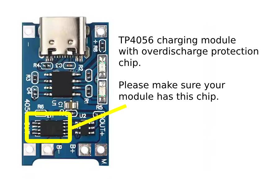
TP4056 may come with or without the overdischarge protection chip. You should always choose the version which has this chip.
Do not power on the ESP32 Marauder while you charge the battery. This thing can trick the TP4056 charging module to overcharge the battery, and you may already know the consequences of such action (the battery can explode if overcharged).
If your TP4056 has a USB-C connector, it won't charge using a dual USB-C cable (cables with USB-C on both ends are not working).
You can add a small heatsink on top of the TP4056 Charging module. The chip tends to get hot and by adding a heatsink, you will improve the charging process.
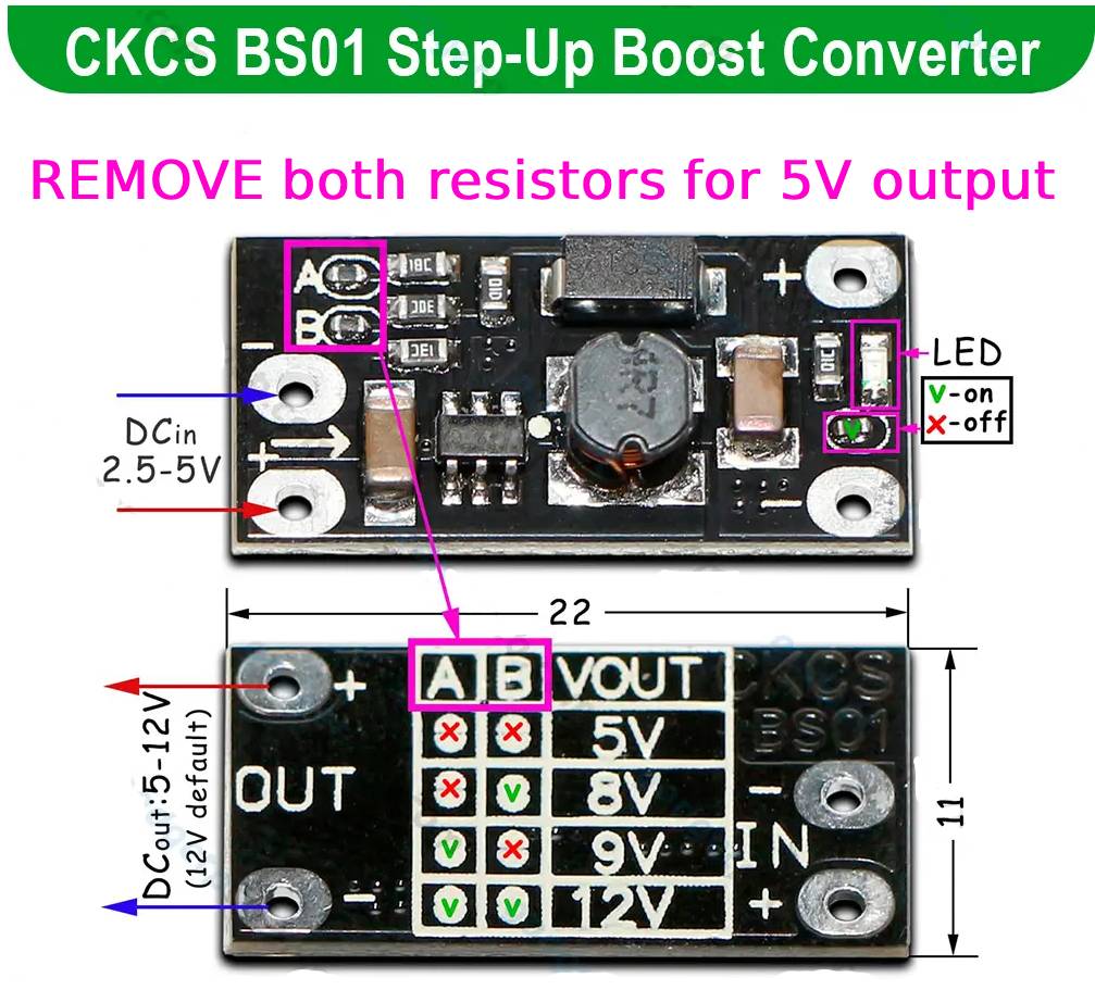
It has 2 resistors (A and B) on the front side. Remove both of them to set the output to 5V. You can use a soldering iron to do so.
If you finished this step, you can now start Adding a GPS Module