Troubleshoot Network - softerhardware/Hermes-Lite2 GitHub Wiki
Introduction
In most cases the HL2 makes network connections with no issues at all. When there is a problem, troubleshooting may be more difficult than one might think initially, for many different reasons.
The HL2 user community uses many different SDR applications running on all the major operating system, and presumably even some 'applications' implemented in hardware with no operating system. The users have a lot of different network configurations, from directly attaching the HL2 to a computer, to attaching it via another network element (bridge, switch, router) and over different distances (local or remote operation). This makes it impossible to come up with a "one size fits all" approach.
As mentioned elsewhere, the HL2 is FPGA-based, so it has no general purpose processor on board. This means it can do signal processing at high speed but it does not have a general purpose network stack on board, nor can it buffer a large number of network packets. The fact that it can do DHCP is a pretty impressive accomplishment.
Please keep in mind the first answer to the first FAQ question: "The Hermes-Lite 2.0 is an experimental project which targets homebrewers". This means it is expected that you will be OK if you need to tinker a bit to get it working. Given it is a software defined radio, a lot of the tinkering is going to be with software. In this section we deal with network issues, so a working knowledge of networking topics is very helpful. I have provided a glossary section below that defines many of the terms I use and provides links to the most relevant Wikipedia pages.
Issues with the initial out-of-the-box network connection
Is it the hardware?
The first thing you might want to do is figure out if you are experiencing a hardware problem or a software or network problem. Note that all the factory made units are tested for proper operation before they leave the factory. Regardless, it is a good idea to troubleshoot the hardware first then move on to the network and finally the software. This is because the hardware provides very reliable indications of what it thinks is going on.
The best way to troubleshoot the hardware is to use the LEDs on the front panel. These LEDs are described on our external connections page. This section focuses on using those LEDs to troubleshoot network issues. Below is the same picture you will find on that page:
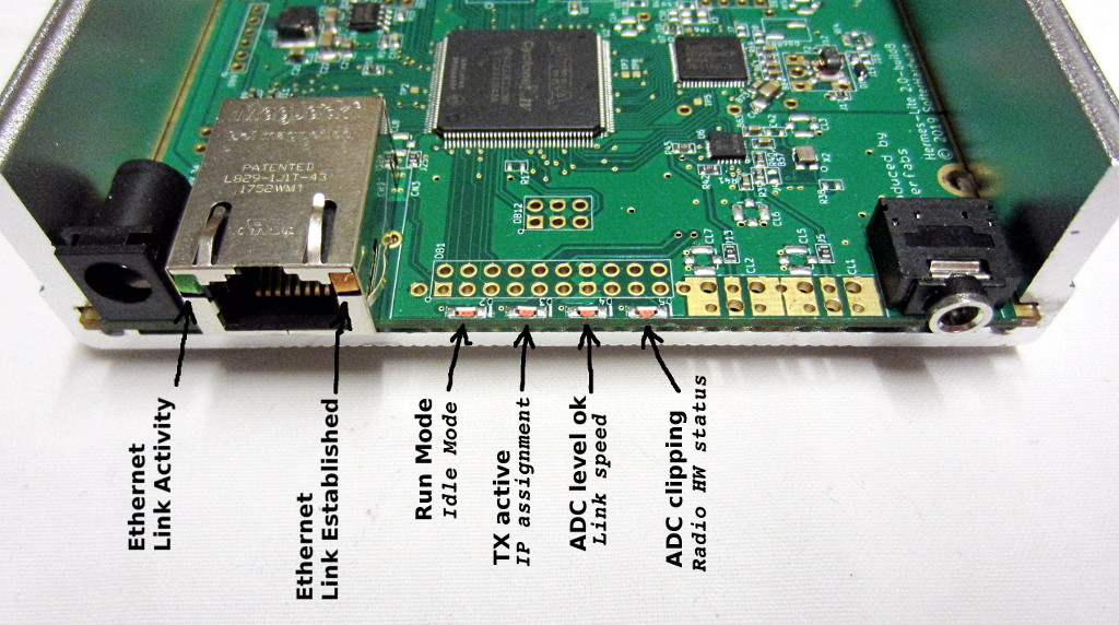
The four LEDs on the board are D2, D3, D4 and D5. If you look closely at the picture you can see they are labeled on the printed circuit board. In this case they are labeled upside down due to the way the photo was taken.
The first LED to look at is the left-most one called "D2", labeled "RUN/clk" on the front panel, which indicates Run Mode vs. Idle Mode.
If D2 is on, you are in Run Mode which means the HL2 has made an initial connection with the SDR Application so the issue is software. The best way to resolve this kind of problem will be to review the HL2 Google Group to see if any other users of this software have encountered similar problems, or reach out to the support channel (typically another online group) that supports that software to see if they can assist.
If D2 is off, the Ethernet chip is not seeing a clock signal at the physical level, which is often a sign of a bad Ethernet cable or a bad Ethernet port. This should be treated as a hardware problem.
If D2 is flashing, the Ethernet chip is seeing a clock signal so we do have some connectivity at the physical layer, yet we are in Idle Mode so the SDR application has not connected with the HL2, so we need to investigate further
I recommend skipping over D3 for now to look at the next LED, D4, labeled "ADC-75/spd" on the front panel, which indicates Link Speed when we are in Idle Mode.
If D4 is off, the Ethernet link speed negotiation has failed, or the path between the FPGA and the Ethernet chip has failed. Since this path is tested at the factory, chances are that this is an issue with poor signalling at the Ethernet physical interface and is thus a physical layer problem that needs to be resolved. Typically this is an issue with the grade of Ethernet cable chosen (it needs to be CAT5 or better, capable of gigabit Ethernet), or the seating of the connector at either end, or a bent pin within a connector, or some corrosion on the pins of the connectors. Try inspecting the connectors to look for damage or corrosion, and/or try different cables, and/or re-seating the connectors, then power-cycling the HL2 so Ethernet link speed negotiation will be repeated.
If D4 is on or flashing, Ethernet link speed negotiation has succeeded at either 100 Mbps rate (flashing) or 1 Gbps (on) rate. We can be confident this is not a hardware issue.
Is it a problem with IP address assignment?
It often is, but let us narrow things down and maybe rule out some other potential issues first.
Assuming we are in Idle Mode (Led "D2" is flashing), the next LED to examine is "D3", labeled "TX/ip" on the front panel, indicating TX Active / IP Assignment.
If D3 is on, an IP address has been assigned via DHCP. If this is lit yet we are still in Idle Mode, we know the HL2 is connected to the infrastructure yet the SDR application is not able to communicate with the HL2. The most likely reason for this is an issue with firewall software installed on the computer running the SDR application, or on a network device in between the computer running the SDR application and the HL2. Note that UDP port 1024 is the main port used when communicating with HL2 and UDP port 1025 is used as a fallback for firmware update when communcation with port 1024 fails.
If D3 is off, HL2 IP address assignment has not (yet) succeeded. This is typically a temporary state with 'on' or 'flashing' becoming the normal state fifteen seconds after power is applied.
If D3 is flashing, then HL2 IP address assignment has succeeded via fixed IP or APIPA. APIPA is described further in the next section and in the glossary. APIPA is attempted if DCHP fails in the first 15 seconds after powerup. This could be exactly what you want to see happen (a fixed IP or APIPA address is used) or it may not be (DHCP fails so APIPA is used as a fallback, or a fixed IP is used when you don't expect one to be used) so let's discuss this further.
What is APIPA?
APIPA stands for Automatic Private IP Addressing. It is a fallback path used when a DHCP-enabled network client fails to get an IP address. This mechanism has been in Windows since Windows 98, so it is widely deployed.
To get an address, the client is expected to select an address in the range 169.254.1.0 to 169.254.254.255 with netmask 255.255.0.0. In the case of HL2 with factory defaults, IP address 169.254.19.221 with netmask 255.255.0.0 is always tried first. The client then sends an ARP request asking for the MAC address corresponding to the chosen IP address. If it receives a reply it knows that IP address is already in use so it generates a different IP address to try. Eventually an unused IP address will be discovered and put into use, or an IP addressing error will be declared. LED D2 is off when an IP addressing error has been declared.
What is the expected IP address assignment behavior?
Typically the HL2 will be connected to a computer or a network device that hosts a DHCP (dynamic host configuration protocol) server. Pretty much every home WiFi router has a built-in DHCP server that is already set up to provide new IP addresses as new devices are discovered on its network. This behavior makes it easy to move the HL2 to different IP networks.
Note that SDR applications that support HL2 typically support network discovery of HL2 devices regardless of what their IP addresses are, so the HL2 should not require a known address.
If you want an IP address that does not change, typically the DHCP server inside most routers can be configured to provide the same IP address for the HL2, given that you know the MAC address that the HL2 will use. Pretty much every home WiFi router has a web-based configuration screen with a way to manage this built-in DHCP server it uses to assign IP addresses based on the MAC addresses presented by clients on its networks. The HL2's default MAC address is determined by the FPGA code we call "gateware".
If you have more than one HL2 on the same network, you will need to change the MAC address of one of the units. The procedure to change the MAC address is given below.
There are cases where a fixed IP address is preferred, usually because of local network administration choices, or lack of a DHCP server. Assigning a fixed IP address is given below.
While many different network configurations are possible, the most direct path between the HL2 and computer running the SDR application tends to work the best. This means (a) cabling the HL2 directly to that computer, or (b) connecting both via Ethernet cables to the same network device. The problem with (a) is that you need to make sure the computer is providing a DHCP service (which typically they do not, unless you have configured it to do so) or if you have no DHCP service available you know that the HL2 will use the IP address assignment fallback path.
What is the behavior of the IP address assignment fallback path?
When no fixed IP address is set and the HL2 does not receive a DHCP response it will use APIPA. See the section on APIPA above for more details.
Temporarily recovering from an unwanted fixed IP address or MAC address
Try using the same procedure as booting from the factory image: short the CW and PTT pins to ground when power is first applied. This can be done using the front panel 3.5 mm stereo jack called CN4 and labeled "KEY/PTT" whose tip connection is the CW input and ring connection is the PTT input. In this configuration any fixed IP or MAC address stored in the EEPROM is ignored so only DHCP will be used to assign an IP address and if this fails APIPA addressing will be used.
If this helps, you should remove the unwanted fixed IP address or change the MAC address using the procedures below.
Why might there be an unwanted fixed IP address?
There have been several reported cases where fixed IP addresses have been assigned when not wanted. It's not clear how this is happening. The only way to set the fixed IP address is to send a message over Ethernet to the HL2 telling it to install the fixed IP address. The theory is that some software may be doing this unintentionally, or the user is doing this without realizing its impact. We look forward to finding a solution to this problem.
How do I perform address management using the Hermes Lite Python Module?
Please see this page
How do I perform address management using the Quisk Application?
Please see this page
How do I perform address management using the SparkSDR Application?
Please see this page
How can I do a detailed investigation of the data that the HL2 and the SDR application are exchanging?
Note that the following tools and techniques should only be used by those comfortable with advanced networking administration and/or design, and software development. Almost all network troubleshooting problems can be solved just by decoding the HL2's LEDs as described earlier on this page, and do not need these tools.
Having said this, the well-known Wireshark "sniffer" application is available in binary form for many platforms, as well as in source form.
On its own, Wireshark can be helpful because it can display the packets and their data being exchanged between the HL2 and the SDR application. At this level it can tell you if communication is happening or not happening.
If you need to dig deeper, the OpenHPSDR-USB Plug-in for Wireshark is available in source form. Once compiled and installed, it can display many but not all details of the OpenHPSDR "Protocol 1" packets that HL2 supports.
Also, the Hermes-Lite Python Module implements the discovery protocol used by HL2 and its applications. Given it is written in Python, it is relatively easy to use it to provide command and control of the HL2 for troubleshooting, and to add additional debugging output while doing so. This wiki's Address-Management-Python page has examples of using that module.
Issues after the initial out-of-the-box network connection is working
"Relay chatter" during transmit
The relays on the HL2 energize when transmitting. If data from the SDR application is dropped intermittently the relays will energize then de-energize, causing "chatter". There have been some changes to gateware over time to increase buffering. Gateware 20201212_72p8 increased the TX buffer latency to 20 ms and PTT to 12 ms based on some feedback from SDR Console users. The max buffer size is now 70-80 ms. Also, some SDR applications have settings to increase buffering. For instance, with piHPSDR (github.com/dl1ycf) you can set the "PTT hang" to 5 ms and "TX latency" to 30 ms. However, if your network is very lossy, these settings probably will not solve the problem, you will have to address the network loss instead.
Handling the case where the Hermes Lite is in transmit mode and the transmit buffer runs out of samples to transmit is an issue. Ideally this should never happen, the SDR application and the network should be able to deliver samples at an appropriate speed then change back to receive mode. With older gateware, Hermes Lite would just stay in transmit mode waiting for software to command it to go into receive mode. With updated gatewware, it waits the "PTT hang" time period then begins the process of going into receive mede. In both cases the transmit signal is corrupted because the transmit buffer is empty so the Hermes Lite transmits quiet.
In the current case, the transmit quiet period is reduced and the user is made aware of the buffer empty problem by seeing and hearing the relays going back to receive mode. If you set the "PTT hang" time to 31ms and the transmit buffer length to 50ms-60ms (which is just over half of the current transmit buffer length) then any relay clicks you hear now indicate that there there are gaps with missing transmit samples which is the root problem to be addressed, presumably by improving the network or the SDR application or the operating system's performance. Since most people are not developers the first thing to look into is the network performance, however applications and operating systems often have settings that may be tuned for better performance or for reducing workload.
Poor performance or disconnections when Hermes Lite is accessed using WiFi
Unlike other network gear which may have a dedicated processor and lots of processor memory, the Hermes Lite only has a FPGA implementation for ethernet. This means that it can offer much lower communication latency but is more susceptible to network packet delays or jitter. WiFi is notorious for longer latency and higher jitter.
WiFi connections often cause problems for low latency UDP connections, and these are the kind required by the Hermes Lite. Often faster WiFi routers are worse, as they "bunch up" the data for higher speed data bursts, and do "smart" spectrum sharing, which can cause large gaps in the UDP data streams.
Given these problems exist, it may be worthwhile to avoid using WiFi anywhere in the path between the Hermes Lite and the SDR application.
Glossary
- APIPA Address: The Internet Engineering Task Force (IETF) has reserved the IPv4 address block 169.254.0.0/16 (169.254.0.0 – 169.254.255.255) for link-local addressing. In the automatic address configuration process, network hosts select a random candidate address within the reserved range and use Address Resolution Protocol (ARP) probes to ascertain that the address is not in use on the network. If a reply is received to the ARP, it indicates the candidate IP address is already in use; a new random candidate IP address is then created and the process repeated. The process ends when there is no reply to the ARP, indicating the candidate IP address is available. Microsoft refers to this address autoconfiguration method as automatic private IP addressing (APIPA).
- DHCP Server: The Dynamic Host Configuration Protocol (DHCP) is a network management protocol used on Internet Protocol (IP) local area networks. A DHCP server must be present on the network. A device connected to the network requests an IP address from the DHCP server using the DHCP protocol; the server assigns a unique address to the device, identifying it for TCP/IP communication, and supplies other network configuration parameters.
- IP Address: An Internet Protocol address (IP address) is a numerical label assigned to each device connected to a computer network that uses the Internet Protocol for communication. An IP address serves two main functions: host or network interface identification and location addressing. IP addresses are written and displayed in human-readable notations, such as 172.16.254.1 in IPv4 format.
- MAC Address: A media access control address (MAC address) is a unique identifier assigned to a network interface controller (NIC) for use as a network address in communications within a network segment. As typically represented, MAC addresses are recognizable as six groups of two hexadecimal digits, separated by hyphens, colons, or without a separator.
- Subnet Mask: A subnetwork or subnet is a logical subdivision of an IP network. For IPv4, a network may also be characterized by its subnet mask or netmask, which is the bitmask that when applied by a bitwise AND operation to any IP address in the network, yields the routing prefix. Subnet masks are also expressed in dot-decimal notation like an address. For example, 255.255.255.0 is the subnet mask for the prefix 198.51.100.0/24.