Build Notes 2.0beta3 - softerhardware/Hermes-Lite2 GitHub Wiki
DEPRECATED PAGE!!!!
This page is deprecated and kept only for historical reference. There have been many changes since beta3. Please see the Hermes-Lite 2.0 Getting Started for current details.
Build Notes 2.0beta3
These are notes to help with Hermes-Lite 2beta3 board bring-up and final assembly.
Schematics
You can find the latest Hermes-Lite 2.0 schematics on www.hermeslite.com. For a Hermes-Lite 2.0beta3 build, please be sure you are using a schematic that says "Rev: 2.0beta3" and is dated July 4, 2017 or later in the lower right corner.
The schematic component prefix "DB" is used for any connector intended for a daughter board. These should only be stuffed as needed.
The schematic component prefix "B" is used for 0.1uF capacitors.
Visual Inspection
Visually inspect your board under magnification. Look for any obvious solder shorts or bridges, misaligned components, or poorly soldered components.
Power Shorts
Use an Ohm meter to verify that no short exists between any of the power supply measurement points shown below. Also verify that no short exist between any power supply measurement point and ground.
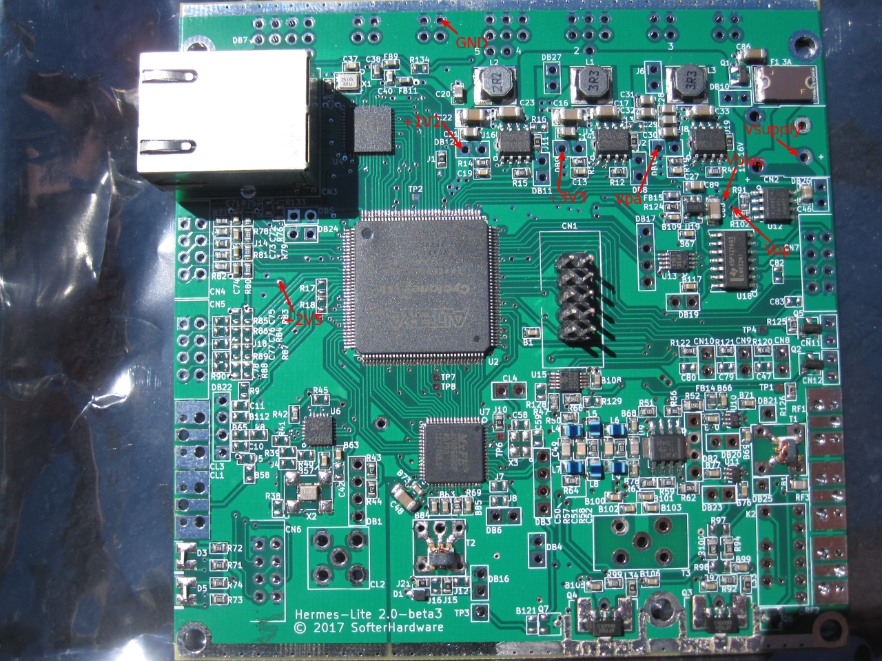
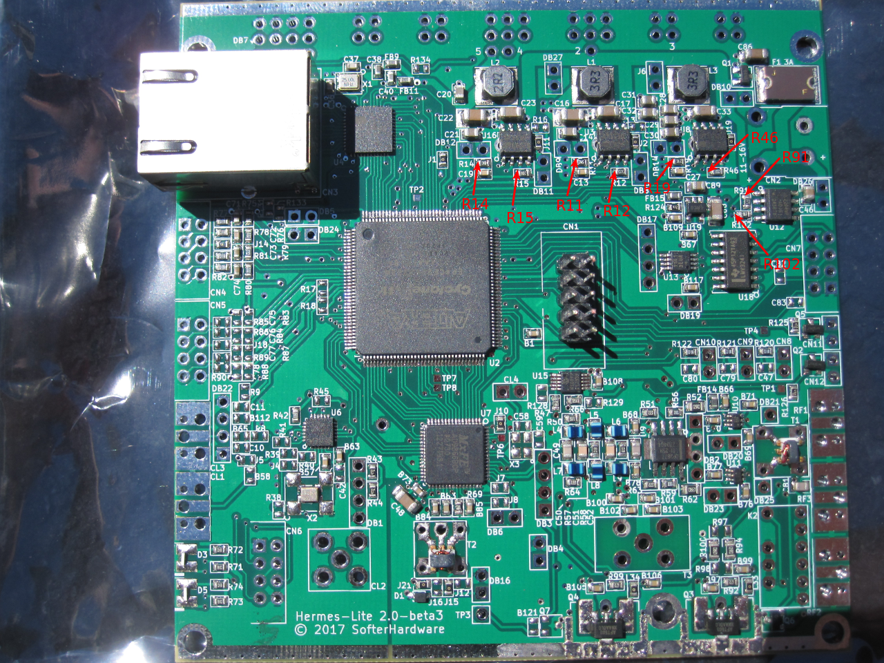
Power Regulator Resistor
To screen for regulators which might produce a wrong output voltage, use an Ohm meter to measure the resistance across all the labeled resistors below. Use the positive probe on end of the resistor that is pointed to by the red arrow. Confirm that your measurements are similar to the measurements in the table below.
| Resistor | Measured Resistance |
|---|---|
| R14 | 6.7K |
| R15 | 6.9K |
| R11 | 9.4K |
| R12 | 8.7K |
| R19 | 15.8K |
| R46 | 1.8K |
| R91 | 2.6K |
| R102 | 1.4K |
Modifications
For proper operation, there are several modifications necessary for the Hermes-lite 2beta3 boards.
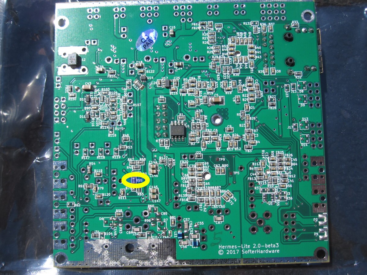
Reduce Gain of RF Preamp
To provide proper power input levels to the PA, R55 should be changed to a 120 Ohm resistor. This is a change made in beta2 that did not make it into the beta3 BOM. Future versions of the Hermes-Lite2 will use a 120 Ohm resistor for R55. For any builder not using the onboard PA and desiring 20 dBm low power out, a 75 Ohm resistor can be used for R55.
Add Resistors for Proper PE4259 Switching
According to this application note, the PE4259 RF switches may require a discharge path to ground when blocking capacitors are used. Add 5K to 10K resistors from the PE4259 side of B70 and B77 to GND as shown in the picture below. The picture shows 10K resistors but 5K resistors will be used in later versions of the Hermes-Lite2. Use larger 0805 or 1210 size resistors to make this modification easier. Keep connections to the added resistors short as they are now part of the TX RF path.

Remove OpAmp from Current and Temperature Sense Paths
To extend the range of the current sensor as well as decrease offsets, it is recommended to remove the opamp U18 from the current sense path to the slow ADC. See this thread for more details. In later versions of the Hermes-Lite 2, there will be no opamp buffer between the current sensor and the slow ADC.
The opamp buffer is also not needed in the temperature sensor path. In later versions of the Hermes-Lite 2, there will be no opamp buffer in the temperature sensor path so that U18 can be exchanged for a smaller 2 opamp IC.
Current readings during RX are bogus. Software will filter these out.
Temperature readings are not accurate to 0.1C. Software will use a coarser resolution so that there is not as much temperature bounce. According to the datasheet, Q6 may benefit from a decouping capacitor near Q6 power and qround. This will be added in later versions of the Hermes-Lite 2.
For now, beta3 testers desiring possibly more precise current measurements especially at the top of the range can lift or even break off pin 8 of U18 as shown below and connect a jumper from U18 pad 8 to U18 pin 10. Likewise, to more closely match later versions of the Hermes-Lite 2, pin 14 of U18 can be lifted or broken off and the jumper from U18 pad 14 to DB19 can be installed. If not FWD/REV power mseasurements are desired, then U18 can be removed entirely.
Future versions of the Hermes-Lite 2 will have similar connections to the schematic in this post with the values changed to R108=270Ohm, R109=1KOhm, R111=0Ohm jumper and B93=100pF. Also, R112 and B95 will not be installed. Resistors are 1%. The resistor divider network for the current measurements requires software to scale the value read by (1270/1000). This allows a maximum Vipa of 3.25*(1270/1000) = 4.13V to be read by the slow ADC. This corresponds to a maximum current of 4.13/50/.04 = 2.065A to be registered. Typically, we see no more than about 1.85A used by the PA.

Adjust Brightness of MagicJack Ethernet LEDs
See this post. Future versions of the Hermes-Lite 2 will use this modification but both R133 and R134 will be 270 Ohm to reuse other BOM lines. This modification changes the ethernet MDIO address and requires gateware 20170904 or later. Also, you can't use later gateware without this modification. If you want to use newer gateware without this mod, see gateware/ethernet/mdio.v and remove the BETA3 ifdef.