STM32F103C8T6 and ST LINK V2 - six0four/ceng317 GitHub Wiki
Getting Started with STM32F103C8T6 and ST LINK V2
based on https://github.com/stm32duino/wiki/wiki/Getting-Started
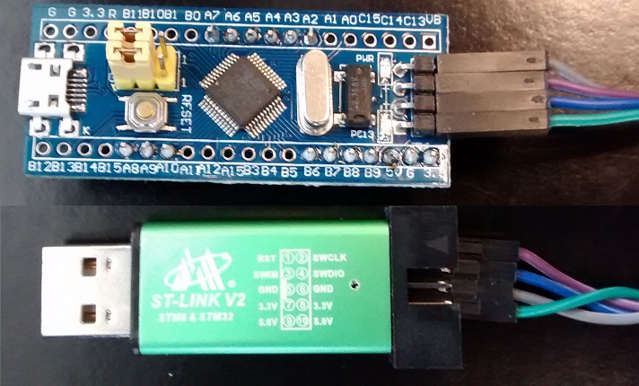
If you have the two items pictured below and are working on a lab computer, proceed with the 3 steps of:
- Adding STM32 board support to the Arduino.cc IDE,
- Installing STM32 and STM32duino drivers; and,
- Uploading the blink code.
Adding STM32 board support to Arduino the Arduino.cc IDE
-
Version 1.6.9 of Arduino software (IDE) is already downloaded and installed in the lab. (Windows, Linux or Mac instructions)
-
Launch Arduino.cc IDE. If the Windows Security Alert dialog pops up, you may cancel it.

-
Click on "File" menu and then "Preferences".
-
The "Preferences" dialog will open, then add the following link to the "Additional Boards Managers URLs" field:
http://dan.drown.org/stm32duino/package_STM32duino_index.json

(alternate preferences approach - VERSION 1.5.0)
-
Click "Ok"
-
Click on "Tools" menu and then "Boards > Boards Manager"

-
The board manager will open and you will see a list of installed and available boards.
-
Select "Contributed" type.
-
Scroll down and select the "STM32F1xx" and click on install (takes some time, use this time to install the STM32 and STM32duino drivers and then return to continue here).

-
After installation is complete an "INSTALLED" tag appears next to the core name.
-
You can close the Board Manager.
-
Now you can find the STM32 boards package in the "Board" menu. Select the desired boards series:

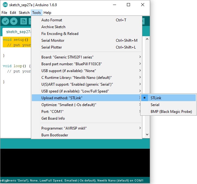
- Select Tools -> Upload methods -> STLink Depending of the board, several upload methods could be proposed, thanks the "Tools > Upload Method" menu.
Installing STM32 and STM32duino drivers
- For the STLink Utility and the STLink Driver you will need to create a free account to download and install them. Do so as long as you find the license agreements, etc. acceptable.

- Install the STM32 ST-LINK Utility via STM32 ST-LINK Utility v4.2.0 setup.exe and click on Next >

- Select Yes as long as you find the license agreements, etc. acceptable.

- Confirm the Destination Location Next >

- Click on Finish:

- Proceed with the device driver installation Next >

- Confirm that you would like to install the device software:

- Click on Finish:

- For the driver notice that the readme.txt says "To install the driver, run stlink_winusb_install.bat in administrator mode, before connecting any ST-Link to the PC." So run the stlink_winusb_install batch file:

- Proceed with the device driver installation Next >
- Confirm that you would like to install the device software:

- Click on Finish:
- Download the STM32duino drivers:

- Extract the download:

- Keep the download:

- Install the drivers:

- Press any key to continue . . .

- Install the COM driver:

- Press any key to continue . . .

Uploading the blink code
- Connect the ST LINK V2 or similar to the board (note that the pinouts on clones are not all the same). Then plug the ST LINK V2 or similar into the computer.
- Select the blink example:

- It will likely appear with code to blink pin 13:

- We need to specify that it is on Port C by adding PC in front of the 13:

- Click on upload:

- If sucessfully uploaded the application should start and the green LED should blink at the rate controlled by the code.

Future work:
Both BOOT jumpers are on the 0 side (versus 1).
On very rare occasions uploading fails. In this situation I have to move BOOT0 jumper to 1 and upload the sketch. Binaries do not run when BOOT0 is set to 1 therefore I move it back. There are also very rare occasions when blue pill does not reset after upload. I have to push the reset button.
Oscilloscope
Firmata
To upload through SWD (STLink), Serial or DFU, STM32CubeProgrammer, ST-LINK Utility, or alternate and command line interface need to be installed. See Upload methods.