G6: Smart Traffic Light System using GSM module - shalan/CSCE4301-WiKi GitHub Wiki
Smart Traffic System
- Smart Traffic System
Group Members
Karim Gemiey
Mohamed El Awadly
Nouran Abdelkarim
Omar Elewa
Github Repository
Motivation
We are using the golden hour rule as our motivation for this project. The golden hour rule says that there is a golden hour between life and death. If you are critically injured you have less than 60 minutes to survive. You might not die right then but something has happened in your body that is irreparable.
Project Idea
Many emergencies/services can easily get delayed during rush hours, and while some of these services can afford the latency of waiting in traffic, other emergencies cannot, and thus, our project is a smart traffic light control system that utilizes a GSM module to aid in the efficient handling of these emergencies/services. It can aid in proper scheduling of arrival and tracking the location of the dispatched car.
Updated Block Diagram
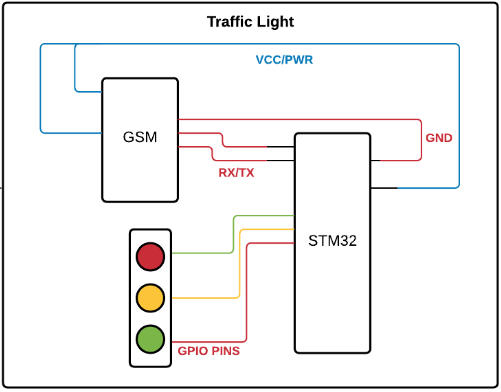
Project Components
- Traffic Light: Responsible for the timely response to the signal provided by the GSM module.
Status Update
Milestone 2 (check Milestone 3 for the modified version)
Setting up ESP32 as a web server
-
ESP32 board works on Arduino IDE
-
It can be accessed locally by reading over WiFi and responding over WiFi
-
Keeps listening for the traffic emergency signal that will be sent over using GSM.
-
After receiving the emergency signal, a loop starts where the webserver keeps accessing the GPS coordinates of the vehicle.
-
When the vehicle is near the traffic lights, the web server sends a signal over to the microcontroller to turn the traffic light green for a predefined amount of time.
Traffic lights logic
- We have implemented the logic of the traffic lights in Keil Vision.
- Through the use of three external LEDs (green, yellow, and red) connected to STM, the relevant traffic light is enabled according to the logic.
- We also used CubeMx for the configuration of UART and the GPIO pins.
Working with GPS Module
-
In order to implement a practical solution that can be implemented in real life scenarios, we decided to integrate GPS module.
-
The GPS module connects to a microcontroller using a UART serial connection
-
It sends data in NMEA-0183 messages format.
-
NMEA-0183 have 2 checksum bytes at the end of most messages, which is of huge importance in our application.
-
We researched how to navigate NMEA-0183 messages
-
NMEA-0183 messages let external devices use selected data collected or computed by the GNSS receiver.
-
Currently considering several NMEA sentences to process, in order to find which one suits our needs best.
-
$GPRMC (Global Positioning Recommended Minimum Coordinates) provides the time, date, latitude, longitude, altitude and estimated velocity.
-
$GPGGA sentence provides essential fix data which provide 3D location and accuracy data, UTC of position fix, Latitude, Direction of latitude, Longitude, Direction of longitude
Working with GSM Module
- We got 3 GSM modules from the workshop to be used for public internet access.
- Also we figured out the APN (Access Point Name) and credentials to access the internet through the GPRS module.
- Started experimenting with GSM with the AT commands
Milestone 3
Some modifications to our original plan were applied as a recommended by our supervisor Dr. Mohamed Shalan, due to time constraints and difficulty to get acquainted with 2 new modules, GPS module and GSM module.
SMS
- We were initially going to use a web server and have the system accessible through the Internet but we decided to use SMS instead, which would make authentication easier and is already secure.
AT Commands used
- "AT" - checking if a connection is established. The response should be OK.
- "AT+CMGF=1" - enables text mode.
- "AT+CNMI=2,2,0,0,0" - reveals the content of the message sent, the number of the sender, and the time of receipt.

Authentication
- We check for the validity of the message by checking the phone number and message content. If the content is not ‘pass’ or the number is not the specific number that is predefined, then nothing happens.
Overriding the Traffic Light
- When the message is authenticated, an interrupt is sent by UART to override the cycle of traffic lights.
Milestone 4
- The GSM module is working when it is connected with the computer on its own.
- We can manipulate it using the serial terminal on our phones.
- However when the STM32 and the GSM are connected, it doesn't work.
- We have implemented the FreeRTOS.
The STM32 doesn't read the GSM module as expected at all. We tried changing the jumpers and the baud rate (9600 and 115200). We also tried using parity bits and tried not using them.
Implementation Notes
Highlighted Configurations
- For the UART interfaced with the GSM module, we used a baud rate of 115200.
- We noted that the messages are terminated using a carriage return character followed by a new line character "\r\n".
AT Commands
- Understanding and dealing with the AT commands, and eventually finding the proper commands needed to get to the contents of the message.
- We faced a difficulty of communicating the GSM module with our STM32, as when we use a serial terminal on our computers to communicate with the GSM module the communication runs smoothly, however, in our C source code, we are still facing difficulties with correcting the data types in order to receive correct strings to be processed.
GSM Module
- Signal is not perfect as the GSM model we use requires an antenna for better signal.
- Trying to automate the process by having the STM32 send the AT commands to the GSM module. Currently outputs gibberish.
Traffic Lights Function
void traffic_lights_on(int rounds) {
 switch (rounds % 4) {
 case 0:
  HAL_GPIO_WritePin(GPIOB, Red_Pin | Yellow_Pin, GPIO_PIN_RESET);
  HAL_GPIO_WritePin(GPIOB, Green_Pin, GPIO_PIN_SET);
  HAL_Delay(GREEN_ON_TIME);
  break;
 case 1:
 case 3:
  HAL_GPIO_WritePin(GPIOB, Red_Pin | Green_Pin, GPIO_PIN_RESET);
  HAL_GPIO_WritePin(GPIOB, Yellow_Pin, GPIO_PIN_SET);
  HAL_Delay(YELLOW_ON_TIME);
  break;
 case 2:
  HAL_GPIO_WritePin(GPIOB, Yellow_Pin | Green_Pin, GPIO_PIN_RESET);
  HAL_GPIO_WritePin(GPIOB, Red_Pin, GPIO_PIN_SET);
  HAL_Delay(RED_ON_TIME);
  break;
 }
 //rounds++;
}
Functions Responsible For Sending AT Commands
void AT_SEND_RECEIVE(char AT[AT_BUFFER], UART_HandleTypeDef *huart1,
  uint8_t OK[OK_BUFFER]) {
 snprintf(AT, AT_BUFFER, "AT\r\n");
 HAL_UART_Transmit(&*huart1, (uint8_t*) AT, AT_BUFFER, TRANSMIT_DELAY);
 HAL_Delay(TRANSMIT_DELAY);
 HAL_UART_Receive_IT(&*huart1, OK, OK_BUFFER);
}
void AT_CMGF_SEND_RECEIVE(char AT_CMGF[AT_CMGF_BUFFER],
  UART_HandleTypeDef *huart1, uint8_t OK_AT_CMGF[OK_BUFFER]) {
 snprintf(AT_CMGF, AT_CMGF_BUFFER, "AT+CMGF=1\r\n");
 HAL_UART_Transmit(&*huart1, (uint8_t*) AT_CMGF, AT_CMGF_BUFFER,
   TRANSMIT_DELAY);
 HAL_Delay(2 * TRANSMIT_DELAY);
 HAL_UART_Receive_IT(&*huart1, OK_AT_CMGF, OK_BUFFER);
}
void AT_CNMI_SEND_RECEIVE(char AT_CNMI[AT_CNMI_BUFFER],
  UART_HandleTypeDef *huart1, uint8_t message_1[MESSAGE_BUFFER],
  uint8_t message_2[MESSAGE_BUFFER]) {
 snprintf(AT_CNMI, AT_CNMI_BUFFER, "AT+CNMI=2,2,0,0,0\r\n");
 HAL_UART_Transmit(&*huart1, (uint8_t*) AT_CNMI, MESSAGE_BUFFER,
   TRANSMIT_DELAY);
 HAL_Delay(2 * TRANSMIT_DELAY);
 HAL_UART_Receive_IT(&*huart1, message_1, MESSAGE_BUFFER);
 HAL_UART_Receive_IT(&*huart1, message_2, MESSAGE_BUFFER);
}
FreeRTOS Tasks
- We have two tasks: TrafficLightsHandle() and myTask03Start().
- TrafficLightsHandle() is responsible for the simulation of the traffic lights.
- myTask03Start() is responsible for receiving data over UART and parsing the info.
Current Status
We faced technical difficulties that resulted in several hurdles:
- First we had many changes to the plan as we the requirements were changed twice during the three weeks time frame.
- Dealing with the cellular service provider was very time consuming as we found out that the SIM cards were not working properly.
- The Module used (A6_mini) that we were provided lacked antennas which enhanced the strength of the connection.
- There are more than 100 AT commands, which can be used to communicate with the SIM card.
- 30+ AT commands are directly related to how we can access the SMS messages on the SIM card.
- Too much time was spent on figuring out technologies that were omitted from our final project.
- NMEA and GPS module interfacing.
- Web server technologies and GPRS interfacing.
Problems with the SIM card
- Every cellular service provider has a different pattern of messages and communication procedures.
- For example Vodafone Egypt sends countless amount of messages whenever the SIM card is powered on.
- Also they recycle phone numbers as many other messages were sent in the form of notifications that someone tried to call this number.
- Whenever we turned on the module we also received many phone calls.
- This made the testing and debugging phases extremely challenging.
Circuit Illustrations
.jpeg)
2.jpeg)
Demo
Updated Hardware Components
- STM32L432KC Microcontroller
- GSM: A6 Quad-band
- 2 Vodafone SIM Cards (for communication within the network)
- 3 LEDs (green, yellow and red, one for each traffic light)
- 3 100ohms resistors to limit the current flowing to the LEDs.
Updated Software Resources
- Keil Micro-Vision - used for traffic lights logic implementation
- STMCube32MX - used for configuration of UART and GPIO pins in traffic lights implementation
- Tera Term - Used as a serial terminal
- Arduino IDE - Used for the easily configured serial monitor
- STM32CubeIDE - Alternative to Keil Micro-Vision on macOS systems
- Visual Studio Code - For using the collaboration functionality
- STM32 HAL Library
- CMSIS Modules
References
GSM Module Datasheet AT - Receving SMS Calling GSM Module - Test Interfacing GSM Module GSM Tutorial [STM32CubeIDE] (https://www.st.com/en/development-tools/stm32cubeide.html) [STM32CubeMX] (https://www.st.com/en/development-tools/stm32cubemx.html) [Keil Micro-vision] (https://www2.keil.com/mdk5/uvision/) [STM32CubeL4] (https://github.com/STMicroelectronics/STM32CubeL4)