G4: Smart Delivery Box Lock & Monitoring System - shalan/CSCE4301-WiKi GitHub Wiki
Smart Delivery Lock Box and Monitoring System
| Name | GitHub |
|---|---|
| Ahmed Abdelkader | Ahmed-Fawzy14 |
| Ahmed Abdeen | AhmedAbdeen7 |
| Malek Ahmed | malekrouk |
1. The Proposal
Abstract / Elevator Pitch:
The increasing reliance on online shopping has made package delivery a routine part of daily life. However, unattended deliveries are often vulnerable to theft and can be inconvenient for homeowners who are not present or who are busy when a delivery arrives. This creates a need for a real-time, convenient, and secure solution that allows homeowners to monitor and manage deliveries remotely.
This project implements a Smart Delivery Lock Box and Monitoring System using an ESP32-CAM as the main embedded controller. A push button is used as the delivery-event trigger. When pressed, the ESP32-CAM captures an image of the visitor or delivery person, attaches a timestamp from the RTC module, and uploads the image to a cloud server over Wi-Fi. The mobile application displays the captured image and allows the homeowner to approve or deny access.
When access is approved, the ESP32-CAM activates a relay-controlled electric latch to unlock the delivery box for a limited time, after which the system automatically relocks. The system also includes a Bluetooth Low Energy fallback mode that allows direct local control from the mobile application when Wi-Fi or server connectivity is unavailable. This design combines image capture, cloud communication, timestamping, local fallback control, and electronic latch actuation to improve the security and convenience of package deliveries.
Project Objectives & Scope:
Minimum Viable Product (MVP)
- Detect a delivery event using a push button connected to the ESP32-CAM.
- Capture image(s) when the push button is pressed.
- Timestamp captured images using an RTC module connected over I2C.
- Transmit captured images and timestamps to a cloud server over Wi-Fi.
- Allow the user to view captured images through a mobile application.
- Allow the user to approve or deny access from the mobile application.
- Poll the cloud server for the user’s decision after an image is uploaded.
- Activate an electric latch through a relay-controlled circuit when access is approved.
- Automatically relock the delivery box after a predefined time interval.
- Provide a Bluetooth Low Energy fallback path for local control when Wi-Fi or server connectivity is unavailable.
- Use regulated power rails for the different system voltages: 12V for the latch, 5V for the ESP32-CAM and relay module, and 3.3V for the RTC module.
Stretch Goals
- Capture multiple frames or discard stale frames to improve image quality under changing lighting conditions.
- Use the ESP32-CAM onboard flash LED during capture to improve low-light visibility.
- Maintain a timestamped log of delivery events and access attempts.
- Display lock status and system feedback within the mobile application.
- Add basic failure recovery, including automatic restart after critical initialization failures.
- Add Wi-Fi health monitoring and automatic switching to BLE fallback mode.
- Improve enclosure design and physical robustness of the lock box and locking mechanism.
- Add persistent image storage through an external service such as Cloudinary or Firebase Storage.
Real Life Example:
i-ParcelBox
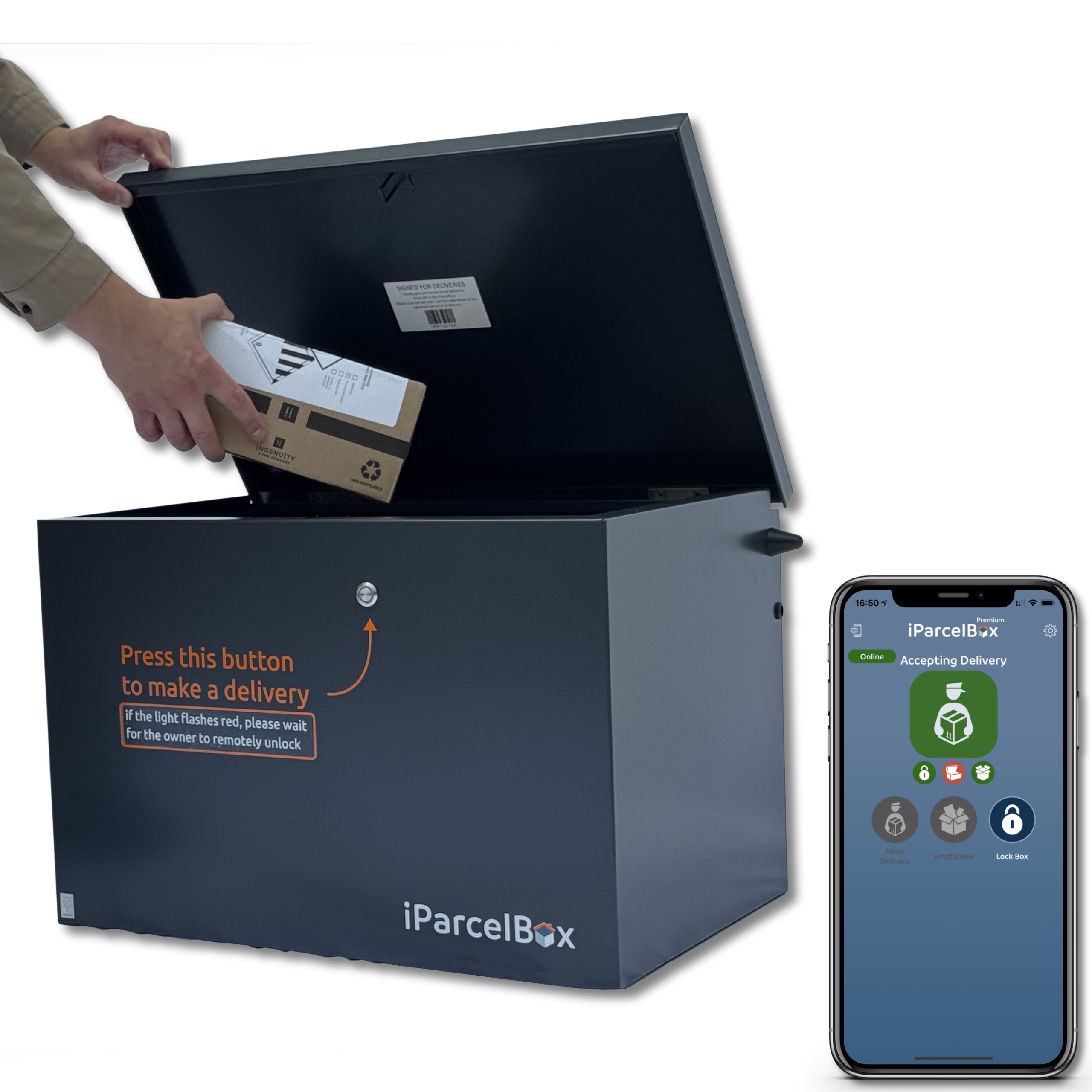
Link to Product: https://www.iparcelbox.com/product/iparcelbox-large/
2. System Architecture
2.1 High-Level Block Diagram:

Subsystem Breakdown
The system is organized around a single ESP32-CAM, which serves as the central embedded controller and integrates image acquisition, communication, timing, and access-control functions. On the input side, the ESP32-CAM interfaces with a push button and a DS3231 RTC module. The push button acts as the delivery-event trigger, while the RTC provides the date and time used to timestamp captured images and access events.
The image acquisition subsystem is based on the ESP32-CAM onboard OV2640 camera. When the trigger button is pressed, the firmware captures an image, attaches a timestamp, and prepares the image for transmission. The onboard flash LED may be enabled briefly before capture to improve visibility in low-light conditions.
The wireless communication subsystem supports both primary cloud communication and local fallback control. Under normal operation, the ESP32-CAM connects to Wi-Fi and communicates with a cloud server using HTTPS. After a trigger event, the ESP32-CAM uploads the captured image and timestamp to the server. The mobile application retrieves the image from the server and allows the user to send an unlock or deny response. The ESP32-CAM then polls the server’s command endpoint to receive the decision.
If Wi-Fi or server communication remains unavailable for a defined period, the system switches to Bluetooth Low Energy fallback mode. In this mode, the mobile application can connect directly to the ESP32-CAM over BLE and send a local control command without requiring internet access. This fallback path improves reliability when the cloud path is unavailable but the user is physically near the box.
The access-control subsystem uses a relay-controlled electric latch. The ESP32-CAM drives the relay input through a GPIO-controlled output stage. When an unlock command is received from the cloud path or BLE fallback path, the ESP32-CAM activates the relay, allowing 12V power to reach the electric latch through the relay COM and NO contacts. The latch remains unlocked for a predefined interval and is then automatically relocked by the firmware.
The power subsystem uses a 12V adapter as the main supply. The 12V rail powers the electric latch through the relay contacts, while DC-DC buck converters generate regulated 5V and 3.3V rails. The 5V rail powers the ESP32-CAM and relay module, while the 3.3V rail powers the RTC module. All grounds are tied together to provide a common reference, while the positive voltage rails remain separate.
3. Hardware Design
Components List
| Component | Photo | Link / Source |
|---|---|---|
| ESP32-CAM | 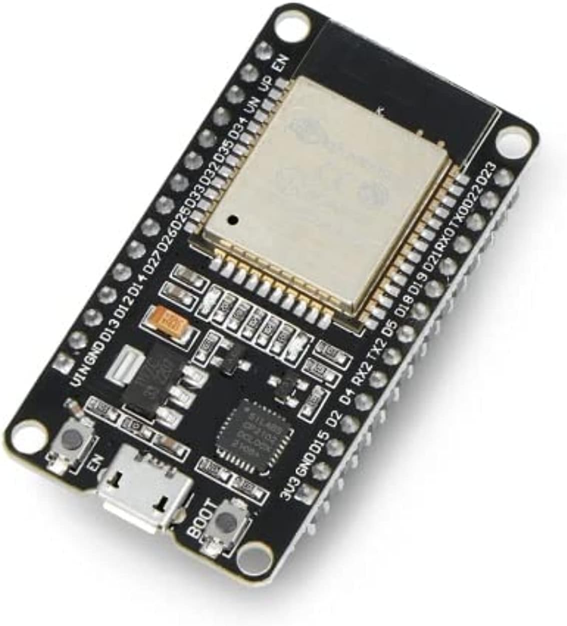 |
Product link |
| Electric Latch | 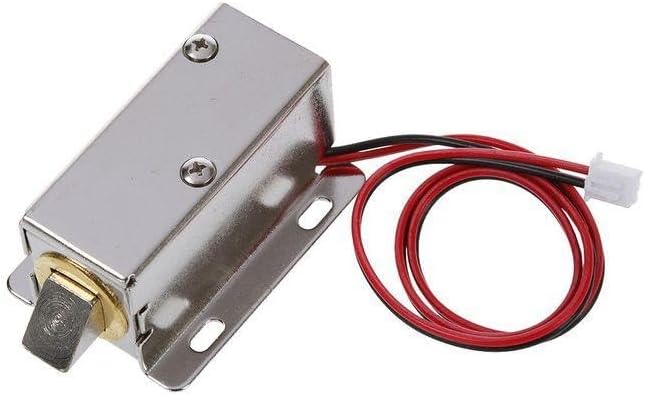 |
Product link |
| 5V Relay Module |  |
Reference page |
| RTC Module | .webp) |
In the Lab |
| Push Button |  |
Reference page |
| Buzzer | 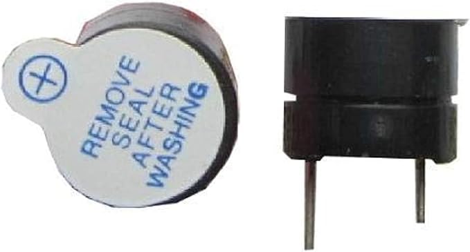 |
In the Lab |
| Green LED |  |
In the Lab |
| 12V DC Adapter |  |
Local / electronics store |
| 5V DC-DC Buck Converter |  |
Reference page |
| 3.3V DC-DC Buck Converter | |
Makers Electronics |
| Female DC Jack Terminal Adapter | Makers Electronics | |
| 2N2222 NPN Transistor |  |
Reference page |
| 10kΩ Resistor |  |
In the Lab / electronics store |
| USB-to-TTL Programmer |  |
Local / electronics store |
| Jumper Wires |  |
In the Lab / electronics store |
Schematics & Wiring
The system uses three main voltage rails: 12V, 5V, and 3.3V. The 12V adapter provides the main input power. The 12V rail is used directly for the electric latch through the relay contacts, while two DC-DC buck converters generate the regulated 5V and 3.3V rails used by the control electronics.

Power Wiring
12V adapter + ├── 5V buck converter IN+ ├── 3.3V buck converter IN+ └── Relay COM
12V adapter - ├── 5V buck converter IN- ├── 3.3V buck converter IN- └── Latch -
Bill of Materials (BOM)
| Component | Part Number / Specification | Quantity | Estimated Unit Cost (EGP) | Estimated Total Cost (EGP) | Datasheet / Reference |
|---|---|---|---|---|---|
| ESP32-CAM | AI-Thinker ESP32-CAM with ESP32 + OV2640 camera | 1 | 550 | 550 | ESP32-WROOM-32 Datasheet, OV2640 Datasheet |
| Electric Latch | 12V DC solenoid/electric latch | 1 | 500 | 500 | Product page |
| Relay Module | 5V single-channel relay module, usually SRD-05VDC-SL-C relay | 1 | 35 | 35 | SRD-05VDC-SL-C Datasheet |
| RTC Module | DS3231 real-time clock module | 1 | Lab available | 0 | DS3231 Datasheet |
| Push Button | Momentary normally-open push button | 1 | 1 | 1 | Push button reference |
| Buzzer | Active buzzer, 3.3V/5V compatible | 1 | Lab available | 0 | Buzzer reference |
| Green LED | 5mm green indicator LED | 1 | Lab available | 0 | LED reference |
| 12V Adapter | 12V 5A AC-to-DC adapter | 1 | 150 | 150 | Adapter label/specification |
| LM2596 3A Buck Converter | LM2596 adjustable DC-DC buck converter set to 5V | 1 | 80 | 80 | LM2596 Datasheet |
| LM2596 3A Buck Converter | Adjustable DC-DC buck converter set to 3.3V | 1 | 80 | 80 | LM2596 Datasheet, if LM2596-based |
| Female DC Jack Terminal Adapter | 5.5mm barrel jack to screw terminal adapter | 1 | 10 | 10TBD | DC jack reference |
| NPN Transistor | 2N2222 NPN transistor | 1 | 1 | 1 | 2N2222 Datasheet |
| Resistor | 10kΩ resistor | 1–2 | Lab available | 0 | Generic resistor reference |
| USB-to-TTL Programmer | USB serial adapter, 5V-capable | 1 | TBD | TBD | Adapter reference |
| Jumper Wires | Male-to-male / female-to-female jumper wires | As needed | Lab available | 0 | Generic wiring |
Power Budget
The system uses a 12V adapter as the main input supply. The 12V line powers the electric latch through the relay contacts, while two DC-DC converters generate regulated 5V and 3.3V rails for the control electronics.
Power Rails
| Rail | Supplied By | Used For |
|---|---|---|
| 12V | 12V 5A adapter | Electric latch through relay COM and NO |
| 5V | 12V-to-5V buck converter | ESP32-CAM, relay module |
| 3.3V | 12V-to-3.3V buck converter | RTC module |
Estimated Current Draw
| Component | Voltage Rail | Estimated Current |
|---|---|---|
| ESP32-CAM during Wi-Fi/camera operation | 5V | 500–700mA peak |
| ESP32-CAM flash LED during capture | 5V | 100–300mA peak |
| 5V relay module | 5V | 70–100mA |
| DS3231 RTC | 3.3V | <5mA |
| LED indicators | 3.3V/5V | 10–20mA each |
| Buzzer | 3.3V/5V | 20–40mA |
| Electric latch | 12V | estimated 0.5–1.5A peak |
5V Rail Estimate
Worst-case 5V current:
ESP32-CAM peak        ≈ 700mA
Flash LED peak        ≈ 300mA
Relay module          ≈ 100mA
LED/buzzer margin     ≈ 100mA
--------------------------------
Estimated 5V peak     ≈ 1.2A
So we need 5V buck converter rated for at least 2A but we used a 3A buck converter which provides a safer margin.
3.3V Rail Estimate
RTC module            < 5mA
Small logic margin     50–100mA
--------------------------------
Estimated 3.3V peak   < 150mA
12V Rail Estimate
Electric latch peak    ≈ 0.5–1.5A
Buck converter input   depends on 5V load
--------------------------------
12V adapter capacity   = 2A
The selected 12V 2A adapter provides enough current for the latch and the DC-DC converters. The 2A rating is the maximum available current; the circuit only draws the current it needs. We could use a higher Ampere adapter to be safer; however, after testing we found that this is enough.
Power Conclusion
The selected power design is sufficient:
12V 2A adapter for latch + DC-DC converters
5V buck        for ESP32-CAM + relay
3.3V buck      for RTC
4. Software Implementation
4.1 Functional Requirements
- The system shall detect a delivery event using a push button connected to the ESP32-CAM.
- The ESP32-CAM shall capture an image when the push button is pressed.
- The ESP32-CAM shall use the onboard flash LED during capture when additional illumination is required.
- The ESP32-CAM shall timestamp captured images using an RTC module connected over I2C.
- The ESP32-CAM shall upload captured images and timestamps to a cloud server over Wi-Fi using HTTPS.
- The cloud server shall make captured images and event data available to the mobile application.
- The user shall be able to view captured images through the mobile application.
- The user shall be able to approve or deny access from the mobile application.
- The ESP32-CAM shall poll the cloud server command endpoint after image upload to receive the user’s decision.
- If the server returns an unlock command, the ESP32-CAM shall activate the relay-controlled electric latch.
- If the server returns a deny command, the ESP32-CAM shall keep the latch locked.
- The ESP32-CAM shall automatically relock the delivery box after a predefined time interval.
- The system shall monitor Wi-Fi/server availability during operation.
- If Wi-Fi/server communication remains unavailable for a defined timeout, the system shall switch to Bluetooth Low Energy fallback mode.
- In BLE fallback mode, the mobile application shall be able to connect directly to the ESP32-CAM.
- In BLE fallback mode, the ESP32-CAM shall accept direct unlock or deny commands from the mobile application.
- The firmware shall periodically attempt Wi-Fi recovery while operating in BLE fallback mode.
- The system shall avoid simultaneous HTTPS operations by using an RTOS mutex.
- The system shall use automatic restart behavior for critical initialization failures such as RTC failure, camera failure, or unrecoverable communication setup failure.
- The system shall maintain timestamped delivery-event records through the server and mobile application.
- The mobile application shall display system event information and allow the user to respond to delivery events.
4.2 Software Architecture:
Description of the firmware design (e.g., Bare-metal Superloop, InterruptRTOS
4.3 Flowcharts & State Machines:
Visual diagrams mapping out the core logic, state transitions, and interrupt service routines (ISRs).
4.4 Key Algorithms:
Explanations of any complex logic used (e.g., PID control loops, digital filtering, sensor fusion).
4.5 Development Environment:
IDE & Build System
Visual Studio Code with the PlatformIO IDE extension was used as the primary development environment for the entire project.
Hardware Programming
The ESP32-CAM was flashed using a USB-TTL serial adapter (CH340/CP2102) since the board has no onboard USB. Flashing required manually pulling GPIO0 to GND to enter download mode before each upload.
5. Testing, Validation & Debugging
5.1 Unit Testing:
5.1.1 Image Capture Submodule
The Image Capture Submodule was tested in multiple stages to verify the behavior of the camera trigger logic, timestamp generation, and image transmission pipeline in isolation.
In the first stage, image capture was tested using a timer-based trigger without integrating the RTC. This was done to confirm that the ESP32-CAM could successfully initialize the camera, capture images at the expected intervals, and send them correctly without depending on external timing hardware. This helped isolate and validate the basic image acquisition and transmission functionality.
In the second stage, the RTC was integrated into the image capture process so that each captured image would include an associated timestamp. To verify the correctness of the RTC output, an image was taken of a physical watch, and the time shown in the image was compared against the timestamp generated by the system. The observed times matched, confirming that the RTC was functioning correctly and that timestamps were being attached accurately.
In the final stage, a 3.3V input was used to simulate the button press signal that will later trigger image capture in the complete system. This allowed the triggering logic to be tested without requiring the final button hardware to be permanently integrated during early development. The test confirmed that the ESP32-CAM correctly detected the trigger signal, captured the image, and followed the expected processing flow.
During these initial tests, image transmission was first verified using a localhost server setup. This allowed the image capture and sending pipeline to be tested in a controlled local environment before moving to remote deployment.
5.1.2 Notification and Response Submodule
The Notification and Response Submodule was also tested in isolation by validating the software components separately before linking them with the rest of the hardware system.
The first step was to develop and test the mobile application independently to ensure that it could correctly display incoming images and provide a user interface for responding to delivery events. This confirmed that the application-side notification and response flow was functioning as intended.
After that, the server was deployed and tested to ensure that it could receive incoming image data from the ESP32-CAM and make it available to the mobile application. Once the server was successfully deployed, the ESP32-CAM was configured with the server URL instead of the earlier localhost endpoint.
A full transmission test was then performed in which the camera captured an image and sent it to the deployed server. The image was successfully received and displayed through the application, confirming that the remote notification path was functioning correctly. This verified that the camera, server, and mobile application could communicate successfully for the notification workflow.
5.2 Integration Testing:
The complete system was tested end-to-end to verify that all hardware and software components operated correctly together. Testing validated the full workflow from trigger detection to remote unlocking of the delivery box.
A push button was used to simulate a delivery event. When triggered, the ESP32-CAM captured an image, retrieved a timestamp from the RTC module, and uploaded the data to the cloud server over Wi-Fi. The mobile application successfully displayed the image and allowed the user to send unlock or deny commands. The ESP32-CAM then received the command, controlled the relay, activated the electric latch, and automatically relocked the box after a predefined timeout.
Bluetooth fallback mode was also tested by disabling Wi-Fi connectivity. In this mode, the mobile application connected directly to the ESP32-CAM through BLE and successfully controlled the latch without requiring internet access.
The firmware was tested using two FreeRTOS tasks running on separate ESP32 cores to ensure that trigger detection remained responsive while network communication was active. Repeated trigger events and continuous operation were also tested successfully without requiring manual resets.
5.3 Challenges & Solutions:
Challenges & Lessons Learned
-
Wi-Fi and BLE Limitation
- Wi-Fi and BLE could not run reliably at the same time on the ESP32-CAM.
- BLE was implemented as a fallback communication method when Wi-Fi is unavailable.
-
Power Supply Design
- Different modules required different voltages:
- 12V for electric latch
- 5V for ESP32-CAM
- 3.3V for RTC
- Used a main 12V supply with step-down converters.
- Different modules required different voltages:
-
Case and Mechanical Design
- The enclosure required accurate measurements for buttons, LEDs, keypad, and ESP32-CAM placement.
- ESP32-CAM dimensions were obtained online and integrated into the enclosure design.
-
Upload Blocking Trigger Detection
- Trigger button became unresponsive during server polling due to blocking HTTP requests.
- Fixed using two FreeRTOS tasks on separate ESP32 cores:
cameraTaskfor trigger handlingpollTaskfor network communication
- Improved responsiveness and continuous trigger detection.
-
iOS Push Notifications Setup
- APNs token returned null on first attempt due to iOS registration delay.
- Fixed by implementing a retry loop with delays before fetching the FCM token.
- Required uploading an APNs authentication key (.p8) to Firebase Cloud Messaging.
-
Android Build Failures
- NDK installation failed due to insufficient disk space during Gradle build.
- Resolved by freeing disk space and using --android-skip-build-dependency-validation flag.
- Package name mismatch between google-services.json and the app required re-registering the Android app in Firebase.
-
Wireless ADB on Windows
- Samsung Galaxy A06 was not recognized by Flutter due to missing ADB PATH configuration and charge-only USB cable.
- Resolved using Wireless ADB debugging after configuring platform-tools in system environment variables.
-
Railway Ephemeral Filesystem
- Images saved to disk are wiped on every redeploy since Railway does not persist the filesystem.
- Acceptable for demo purposes; permanent storage solution (e.g. Cloudinary) identified as a future improvement.
-
AppBar Overflow on Android
- Title text overflowed on smaller Android screens due to fixed font size.
- Fixed by wrapping the title in a Flexible widget with TextOverflow.ellipsis.
-
Wi-Fi Reliability and Failure Recovery
- ESP32-CAM did not always connect reliably to Wi-Fi during startup; if initialization failed, the board could remain stuck and require a manual reset.
- Added dedicated Wi-Fi connection and reconnection routines, disabled Wi-Fi sleep, and introduced automatic restart after repeated failures.
- Major startup failures related to Wi-Fi, the RTC, or the camera were handled using auto-restart instead of leaving the system stuck in an infinite error state.
-
Low-Light Image Capture
- Images captured in dark scenes were not clear enough due to insufficient illumination.
- Enabled the onboard flash LED of the ESP32-CAM during image capture turned on just before capture and off immediately afterward to improve visibility.
-
Trigger Simulation Before Button Integration
- The real pushbutton hardware was not yet available, but the image capture trigger logic still needed to be tested.
- Used a 3.3V digital trigger input to simulate the button press, with a Nucleo board driving the trigger pin HIGH so the same logic could be tested before swapping in the real button.
-
Single-Capture Trigger Behavior
- System originally captured only one image per trigger event, limiting repeated testing and continuous operation.
- Updated the trigger logic to continuously monitor the trigger input and support repeated image captures instead of stopping after the first one.
6. Results & Demonstration
6.1 Final Prototype
The following images show the final assembled prototype, including the ESP32-CAM, power regulation stage, relay/latch wiring, RTC module, and enclosure setup.
.jpeg?raw=true)
.jpeg?raw=true)
.jpeg?raw=true)
.jpeg?raw=true)
.jpeg?raw=true)
.jpeg?raw=true)


6.2 Video Demonstration
The following videos demonstrate the smart delivery lock system operating in real time, including image capture, server communication, and latch activation.
6.3 Performance Metrics
The prototype was evaluated based on its ability to capture an image, send it to the server, receive a command, and activate the electric latch. The system successfully demonstrated the main delivery-lock workflow: a trigger event starts image capture, the ESP32-CAM uploads the image, and the relay activates the latch when an unlock command is received.
| Metric | Result |
|---|---|
| Image Capture | Successfully captured images using the ESP32-CAM |
| Server Communication | Successfully sent image data to the server |
| Remote Unlock Control | Relay/latch activation controlled through the system command flow |
| RTC Timestamping | RTC module used to attach timestamps to captured events |
| Power Stability | System tested using regulated 5V and 3.3V DC-DC outputs |
| Backup Access Method | Bluetooth backup planned/implemented as a local fallback option |
7. Project Management
7.1 Division of Labor:
- Ahmed Abdelkader: Worked on all hardware systems, integration and demo.
- Malek Ahmed: Worked on all hardware systems, integration and demo.
- Ahmed Abdeen: Worked on Full Stack App and cloud server and integration.
7.2 Milestone Progress:
Milestone 3:
So far, the Image Capture and Remote Notification Submodule has been completed. The current implemented flow allows a person to press a button, after which the ESP32-CAM captures an image and sends it to the cloud server together with the timestamp from the RTC. The image is then displayed on the mobile application, allowing the user to view the event and respond on whether the box should be unlocked.
The remaining work focuses on completing the Lock Control and Access Submodule. This includes sending the user’s response from the mobile application to the controller, implementing the physical lock/unlock mechanism of the box, and integrating the buzzer and LED indicators to reflect the current box status. In addition, the full communication and control flow between the hardware components and the mobile application still needs to be integrated and tested end-to-end.
The overall project scope remains unchanged and still targets the full Smart Delivery Box Lock and Monitoring System. By Checkpoint B, the goal is to complete all remaining submodules, begin full integration, and update the wiki with integration progress and testing evidence. By Milestone 4, the goal is to have the entire system fully completed, integrated, tested, and ready for the final demo and presentation.
Module Image and Demo


Milestone 4 (Final): The full Smart Delivery Lock Box and Monitoring System has been completed, integrated, and demonstrated. All submodules are functional and working together end-to-end. The Lock Control and Access Submodule was completed, including relay-controlled electric latch actuation, automatic relocking after a predefined timeout, and LED and buzzer feedback indicating the current lock state. The user's unlock or deny response is sent from the mobile application to the cloud server, polled by the ESP32-CAM, and acted upon by the relay circuit. The mobile application was developed in Flutter and deployed on both iOS and Android. It displays captured delivery images with timestamps, supports remote lock/unlock commands over Wi-Fi, and includes a Bluetooth Low Energy fallback mode for direct local control when internet connectivity is unavailable. Real-time push notifications were integrated using Firebase Cloud Messaging, alerting the user immediately when a new delivery image is received. The cloud server was deployed on Railway and provides REST API endpoints for image upload, image retrieval, command queuing, status reporting, and push notification delivery. A web-based gallery was also implemented for browser-based image viewing. The complete system was tested end-to-end including trigger detection, image capture and upload, remote unlock via Wi-Fi, direct control via BLE fallback, automatic relocking, and push notification delivery on both iOS and Android devices
7.3 Timeline:
| Date | Milestone | Deliverable / Task | Duration | Progress |
|---|---|---|---|---|
| Mon, Mar 30, 2026 | Project Kick-off | Project handout issued. Start forming teams and brainstorming ideas. | 1 day | Completed |
| Tue, Apr 14, 2026 | Milestone 1: Team Formation | Team formation deadline. | 1 day | Completed |
| Wed, Apr 15, 2026 | Milestone 2: Proposal Presentation | In-class proposal presentation. | 1 day | Completed |
| Mon, Apr 20, 2026 | Checkpoint A: Wiki/Page Setup | Team project page on the course wiki must be created and populated with the approved proposal. | 5 days | Completed |
| Wed, Apr 29, 2026 | Milestone 3: Progress Presentation & Demo | In-class progress presentation and live demo of at least one major subsystem. | 9 days | Completed |
| Wed, May 6, 2026 | Checkpoint B: Integration Update | Wiki update showing integration status, testing evidence, and remaining issues. | 7 days | Completed |
| Wed, May 13, 2026 | Milestone 4: Final Demo & Presentation | Final in-class presentation, live demo, final code, and completed wiki page due. | 7 days | Completed |
8. Appendices & References
8.1 Source Code Repository:
8.2 References:
Hardware References
- Espressif Systems, “ESP32-WROOM-32 Datasheet.”
- Espressif Systems, “ESP32 Camera Driver / esp32-camera Repository.”
- OmniVision, “OV2640 Camera Sensor Datasheet.”
- Analog Devices / Maxim Integrated, “DS3231 Extremely Accurate I2C-Integrated RTC Datasheet.”
- Songle Relay, “SRD-05VDC-SL-C Relay Datasheet.”
- Texas Instruments, “LM2596 SIMPLE SWITCHER Power Converter Datasheet.”
- STMicroelectronics, “2N2222 NPN Switching Transistor Datasheet.”
- Vishay, “1N4007 General Purpose Rectifier Datasheet.”
- Components101, “Push Button Pinout and Working Reference.”
- Components101, “5V Relay Module Pinout and Working Reference.”
Software and Platform References
- Espressif Systems, “Arduino ESP32 Wi-Fi API Documentation.”
- Espressif Systems, “Arduino ESP32 Bluetooth/BLE API Documentation.”
- Espressif Systems, “ESP-IDF FreeRTOS Overview for ESP32.”
- PlatformIO, “Arduino Framework Documentation.”
- FlutterFire, “Firebase Cloud Messaging for Flutter.”
- Railway, “Data & Storage Documentation.”
- Railway, “Volumes Documentation.”
- Random Nerd Tutorials, “ESP32-CAM Take Photo and Save to MicroSD Card.”