G1: Home Security System - shalan/CSCE4301-WiKi GitHub Wiki
Home Security System
Authors:
- Donia Ghazy - https://github.com/doniaGhazy
- Marwan Eid - https://github.com/marwan-eid
- Mohammed Abuelwafa - https://github.com/Osos3006
Motivation:
Security nowadays is a matter of vital importance especially in homes and local stores for example. There are multiple systems developed for the purpose of security monitoring and protection. Cameras and smart lock systems are implemented in such places to enhance their security and to prevent thefts and heists as well. A home security system protecting one’s family and property and deterring burglars would offer one piece of mind whether s/he is sleeping or away from home.
Proposed Solution:
- Our project uses a Passive Infrared Radiation (PIR) sensor, a camera, a buzzer, a led , an ESP32 cam module for Wi-Fi connectivity and having a webserver to implement a home security system.
- The PIR sensor detects the change in infrared radiation of warm blooded moving objects in its detection range (7 meters). Such change will be reflected as a digital output generated from the sensor.
- When the system is running and a burglar gets into the detection range of the PIR system, the following happens:
- the camera is triggered and an instant picture of the burglar is sent to the owner (through a web server.)
- The buzzer rings imitating an electronic alarm
- the led will be turned ON representing the lightings of the House.
System block Diagram:

Input:
- Existence of a warm blooded person using the PIR sensor
Output:
- GPIO output signal for the LED.
- GPIO output signal for the Buzzer.
- Live footage of the Bulgar using the ESP32 CAM module.
Communication:
- UART for the communication between the ESP32 Cam and the STM32.
- Wi-Fi for the communication between the ESP32 Cam and any user Device in order to view the images.
Components:
Hardware Components:
- STM32l432kc → main MCU
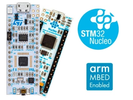
- STM32 is an ARM cortex M4 based processor
- it is used as Our main microcontroller as a central processing unit where it gets the input from the sensor, sends the output signals to the buzzer and the LED, and communicate to the ESP32 cam when to capture the Photos
- Ai-Thinker ESP32-CAM module

- The ESP-32 CAM provides the system with Wi-Fi connectivity
- The ESP-32 CAM takes the character 'c' from the STM32l432kc through the UART link implemented on GPIO-16 (UART 2 in ESP32-cam only has an RX which is on GPIO-16), then it takes an image using the OV260 camera module mounted on it, stores the image on the SPI flash file system (SPIFFS)
- The ESP-32 CAM enables the system to have a web-server which provides the backend for the user interface. it basically gets the image from the SPIFFS and display it to the user. Moreover, we added an extra functionality for the user to be able to take a picture whenever he wants and display it even without having the alarm triggered in case he wants to check out his outdoors or heard something suspicious.
- Active Buzzer
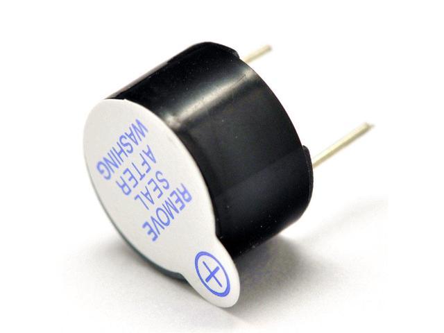
- the buzzer in our system imitates a real electronic alarm in order to produce sound when a burglar is detected.
- LED

- The LED in out system imitates a the lightings of a house where they are triggered using the GPIO output ON signal from the stm32l432kc. In real world context and a production level product would have a relay module that takes this output and lights the lightings of the house.
- HC-SR501 → PIR motion detection sensor

- The PIR sensor has 3 Pins ( VCC , GND, Digital Output). The digital Output is 1 when it detects a warm blooded person.
- It has two modes:
- the repeatable mode which recapture motion as it occurs after the duration of High time ends. However, two detections are separated by a period of 3 seconds where the Sensor does not capture any motion. the sensor is on the repeatable mode by default and it suits our application.
- the non-repeatable mode which only captures the first instance of motion and sets the output to high for the delay adjust duration, then it goes to low.
- The Sensor has a Delay time adjust which adjusts the period of high time when motion is detected from 5 seconds to 5 minutes. For the purposes of our application, we adjusted it to be 35 seconds.
- The sensor has a sensitivity adjust which adjusts the detection range between 3 meters and 7 meters. we adjusted it to the maximum which is 7 meters for maximum detection range.
- More about the theory of operation can be found here
- USB-to-TTL Module
- The USB-to-TTL Module provides an interface for programming the ESP32-CAM (by connecting the UART interface in addition connecting the GPIO-0 on the ESP32-CAM to ground and pressing reset while uploading the code). Moreover, it provides an interface for Debugging Messages.
Software Components:
- Keil uVision5
Buzz():
- This function turns the buzzer on and is triggered if the PIR sensor detects motion.
- This function generates a standard alarm like sound using a PWM signal by varying the prescaler by iterating through i = 15 to 75 with a step of 3 and the prescaler is assigned 2i
Light():
- This function turns the LED on and is triggered if the PIR sensor detects motion.
main():
- This function includes code that reads the output pin of the PIR sensor to detect whether there is motion or not. In case there is no motion detected, the buzzer and the LED are turned off. If, however, motion is detected, both are turned on, and a flag is sent to the ESP32-CAM to capture a picture every other small delay.
- STM32CubeMX
- Arduino IDE
Libraries:
-
With the Arduino Wi-Fi Shield, this library allows an Arduino board to connect to the internet.
-
We use it for connecting the ESP32-CAM to the machine’s local network.
-
An Async HTTP and WebSocket Server for ESP8266 Arduino.
-
We use it for building the web server.
-
SPIFFS is a file system intended for SPI NOR flash devices on embedded targets.
-
We use SPIFFS in order for the photos captured to be saved in it.
Functions:
CapturePhoto():
- The capturePhoto() function is a JavaScript function that is triggered upon clicking the “CAPTURE PHOTO” button on the web page. The function sends a request on the /capture URL to the ESP32 so that it captures a new photo.
Setup():
In the setup() function, the following is done:
- Serial communication is initialized.
Serial.begin(115200);
- The ESP32-CAM is connected to the machine’s local network.
WiFi.begin(ssid, password);
- SPIFFS is initialized.
SPIFFS.begin();
- Configurations and initializations for the OV2640 camera module are done.
- Cases for when the ESP32-CAM receives a request on a URL are then handled.
-
If the ESP32-CAM receives a request on the root / URL, the HTML text to build the home web page with the “CAPTURE PHOTO” and “REFRESH PAGE” buttons is sent back to the client.
-
If the “CAPTURE PHOTO” button is pressed on the web server, a request is sent to the ESP32 /capture URL. Then we set a flag to capture a new picture.
-
If there is a request on the /saved-photo URL, the photo saved in SPIFFS is sent to the connected client.
- The web server is started.
Loop():
capturePhotoSaveSpiffs(void):
- This function is called when the flag to capture a new picture is set to true.
- The function captures a new photo with the camera and saves it to SPIFFS.
checkPhoto(fs::FS &fs):
- This function is used in the capturePhotoSaveSpiffs() function to check whether the captured photo was successfully saved to SPIFFS or not. If not, another photo is captured again.
Not using FreeRTOS was a compromise between the system complexity versus its stability at code changes, WCRT, and priorities. We chose not to complicate the system by adding RTOS since we are not expected to add future changes to the code.
System Implementation:
Circuit:
- motion detected
- No motion
- ESP32 validation that it is connected to STM32. otherwise it loops waiting for the UART connection which is critical to the system.
- ESP32 connected to Wi-Fi + saving images
- Light ON/OFF , Buzzer ON/OFF
- Web Server preview (phase1)
- Web Server Preview (Final)
- Web Server Secured
- Logging out page
Limitations:
- The Esp32 Cam should be placed into a specific angle in order to detect people's faces clearly.
- Esp32 cam is limited to only one client.
- We host the images on SPIFFS meaning that it stores a limited number of images, so in our project we only save one image at a time.
- Images on the server are not automatically refreshed but we need to refresh it manually every time to get the latest captured photo.
- For the User to turn Off or ON either the light or the Buzzer : He has to press 'l' for light and 'b' for Buzzer in a terminal connected to STM MCU through UART. This is going to be addressed in the future works.
Future work:
- To overcome the problem of SPIFFS, we could use the micro SD port in the ESP32 cam and store the images to it. This will give the room to store more images.
- Instead of using LEDs, we could use a relay module and mounting some real lamps.
- We could Implement more functionalities in the web server such as adding support to multiple clients using a network of esp32 cams. This will provide coverage to a higher range from different angles.
- A mobile application that reads the input from the webserver that connects multiple units of out system can be developed as well.
- Scheduling when the system should run and when it should stop is another functionality we could add. We could use an RTC module's internal clock to check whether it falls within a range the user selects the system to run in or not which will give the system timekeeping functionality. The RTC module would have been connected to to the STM32 using I2C, and the user input for the time range would have been fed to the system from the server and then using UART.
- We could provide additional Bluetooth communication between the ESP32 and the STM32 using the HC-05 Bluetooth module.
Challenges
-
We had to use Arduino IDE for the ESP32 cam not the Keil uVision (our main MCU IDE) as it has ready to use libraries and we found it difficult and time consuming to implement the ESP32 webserver and Camera interfacing on the ESP using Pure C on keil without any support from the community. however, the open source community recommended the use of the available libraries on Arduino IDE and that it can be used for production code.
-
The ESP32-CAM have no USB interface which made it difficult to program it, debug it and test the code on its own since the process of programming it includes connecting GPIO-0 and GND. then uploading the code while pressing reset in a specific point of time, then you have to disconnect the GPIO-0 and GND. Finally, you have to reset the system again in order for it to function. Moreover, the ESP32-CAM reset button is on the bottom of the board which made it not friendly for being fixated on the breadboard. hence, we depended on a primitive setup in order to fix the components for testing.
-
The ESP32-CAM has one UART for Debugging information and programming it using a USB-to-TTL module. It has another UART only which has only RX implemented which made it difficult to transmit information from the ESP32 to the STM32 using UART. hence, another solution was figured out which is bluetooth pairing using a BT module like : HC-05 as discussed in the future work.
-
This project was our third attempt for the semester since we had difficulties in the first attempt because the components were not available in Egypt and the second project idea was not feasible. hence, we were stressed in a very short time span to implement our project, test it and present it.