Hyleton 313 Smart Plug - seurat-atreides/Sonoff-Tasmota GitHub Wiki
Intro
Recently I bought a very nice and compact Smart Plug (UK variant) from Aliexpress - a Hyleton 313. This was in fact the smallest smart plug device with UK plug I've ever seen - it is no bigger than an average USB/phone charger:
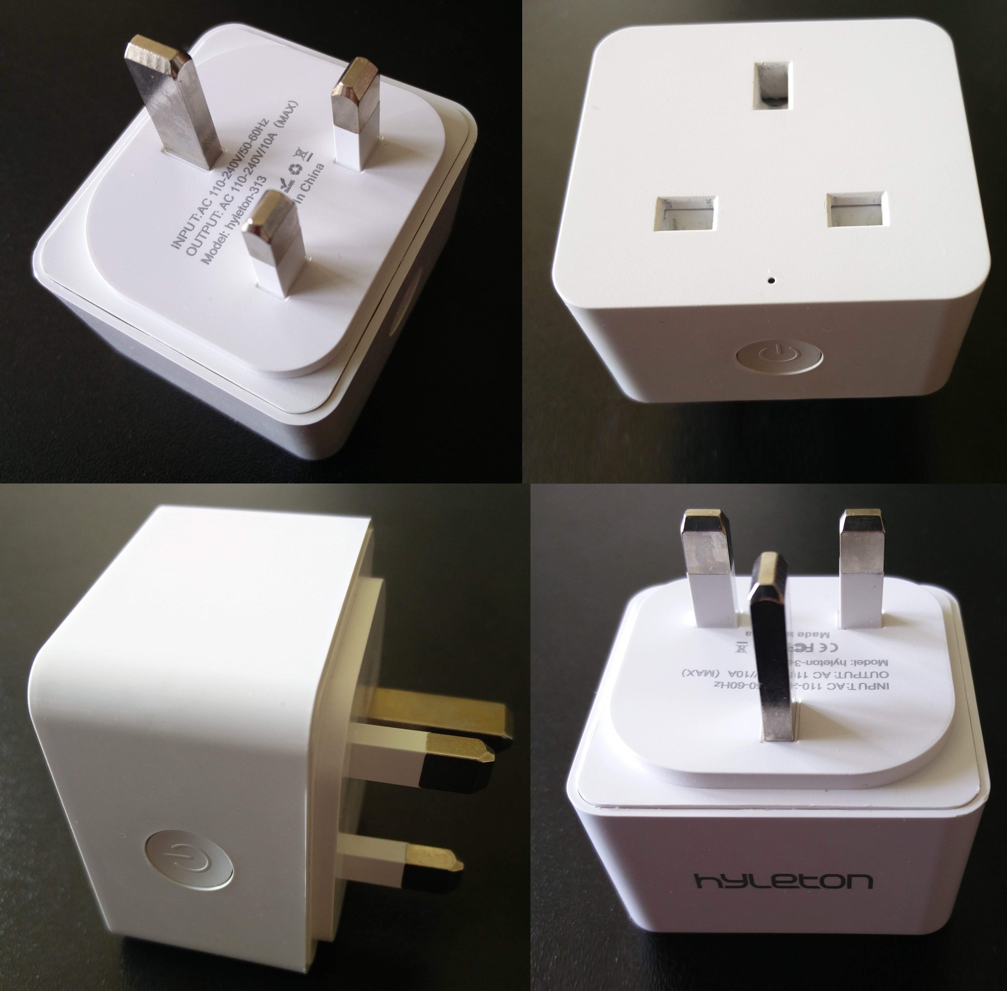
Another good thing is that it is built around a ESP8266 module, which gives us the possibility to change its firmware and install Tasmota.
Open the case
There are no visible screws, however it is not that difficult to open the case using some sharp plastic pry tool and a heat gun (hair dryer on max setting will probably also work). Heat the edge of the plug a bit, then work your way slowly, pry from the middle of each side. Then slowly slide the tool towards the corners and the case will ease enough eventually - open it with a gentle pull.
Once the case is open, the top side of the PCB will be exposed:
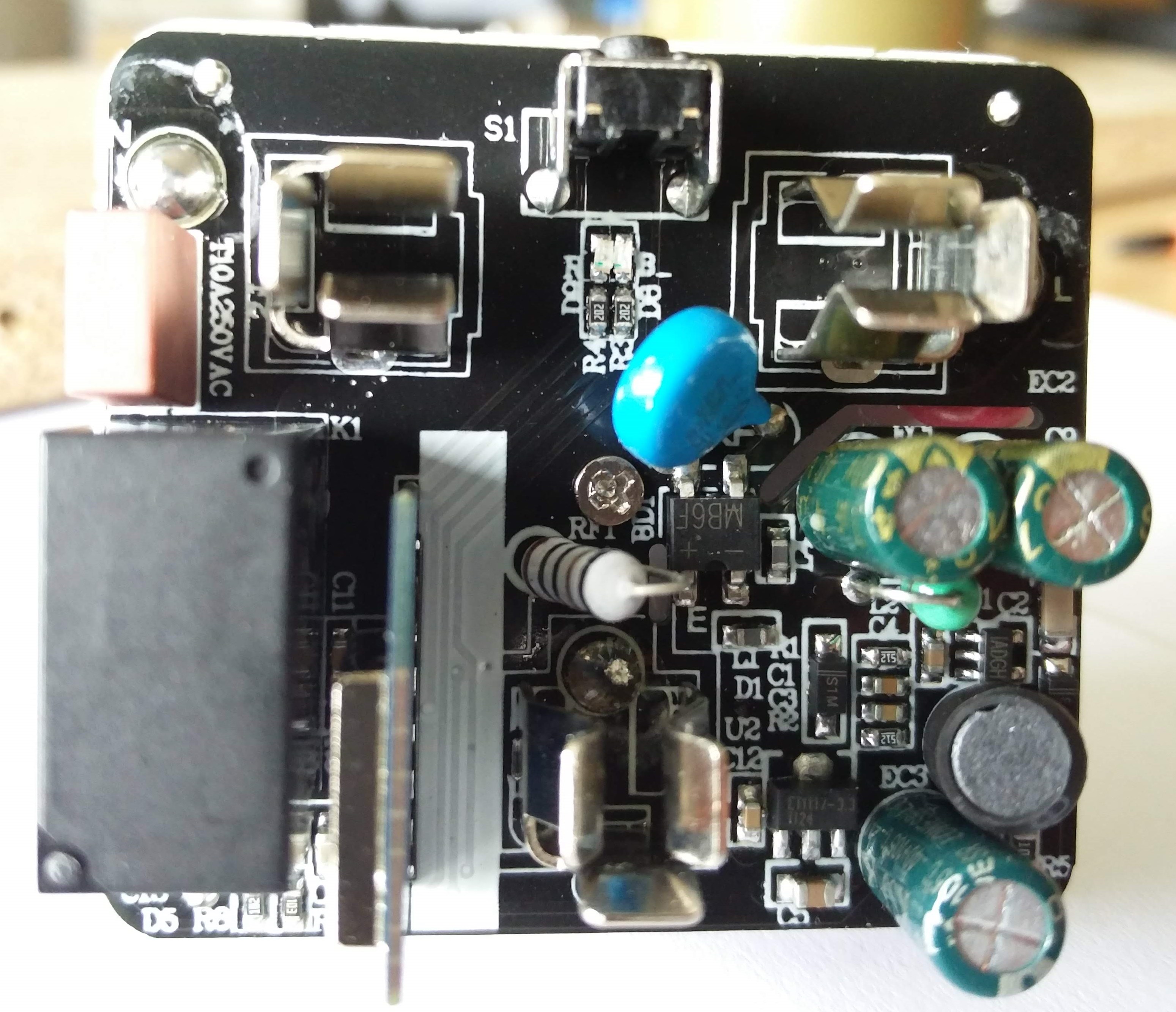
The WiFi module is soldered vertically to the main PCB and sits right next to the relay. In order to get access to its pins, remove the screw from the centre of the PCB. After that the bottom plastic plate, which holds the three mains connector prongs, can be moved a bit to the side without desoldering anything (it is attached with short cables to the PCB, but cables' length is just enough to move it out of the way of the WiFi module's pins).
Here's a view of the bottom side of the PCB:
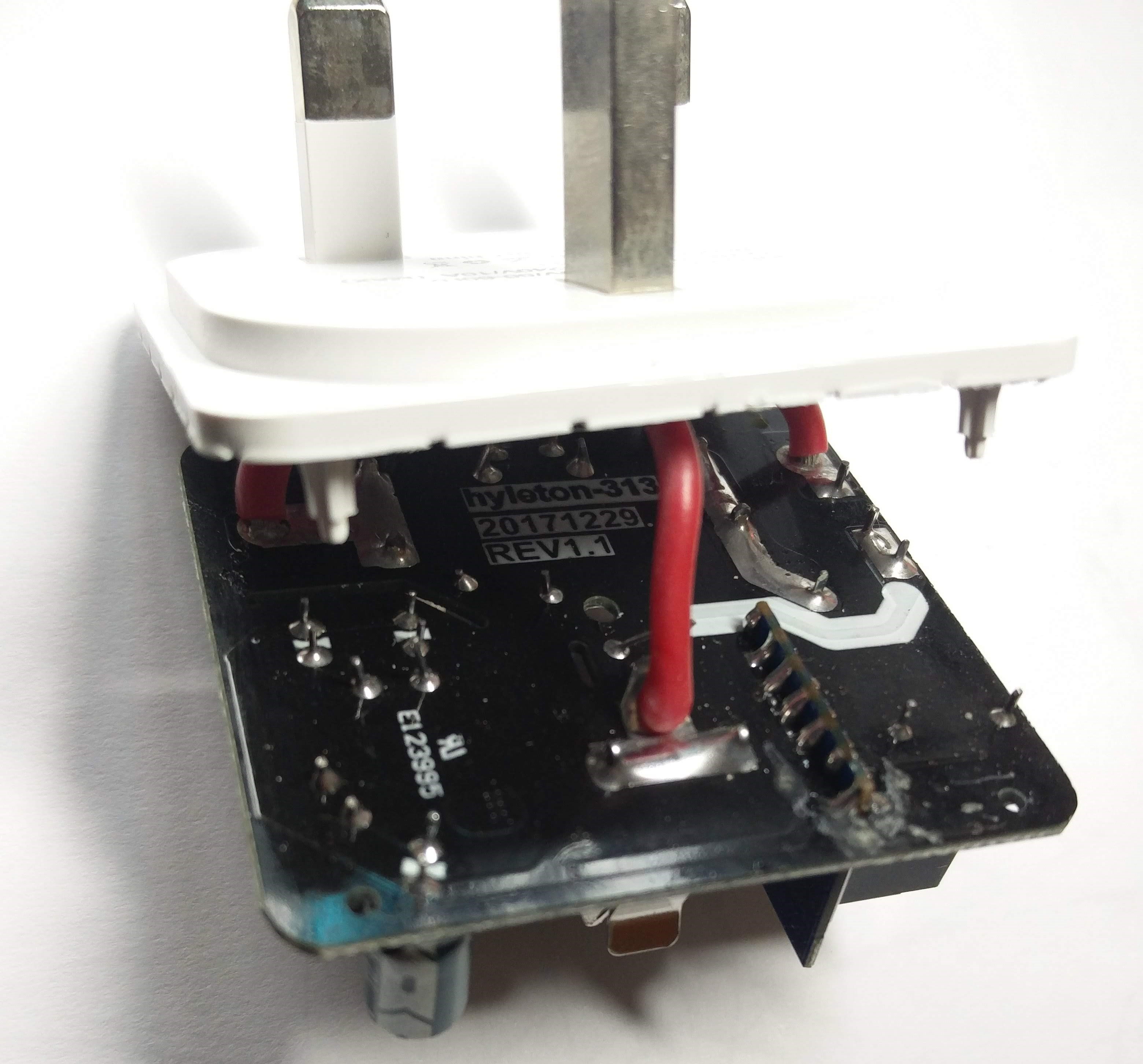
You can see the product labels (product code, date and board revision), as well as the UL number.
WiFi module pins
Here is a close-up view of the module's pins as seen from the bottom of the main PCB:
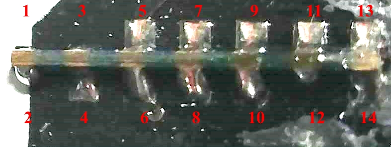
And this is how module pins numbers are mapped (I had to desolder the module looking for labels when I tried to identify it):
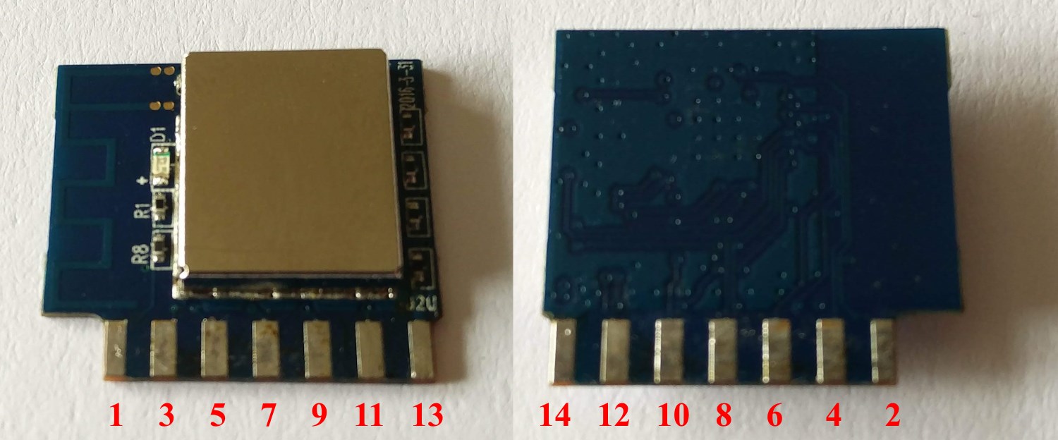
Failed to identify the module, I had remove the metal shielding cap to find the routing of the ESP8266's pins, so I grabbed the multimeter and soon I had the following table:
| Module pin | ESP8266 pin | Pin name | Pin name | ESP8266 pin | Module pin | |
|---|---|---|---|---|---|---|
| 1 | 7 | Chip Enable | Tout (ADC) | 6 | 2 | |
| 3 | 9 | MTMS / GPIO14 | MTDI / GPIO12 | 10 | 4 | |
| 5 | 12 | MTCK / GPIO13 | MTDO / GPIO15 | 13 | 6 | |
| 7 | 15 | GPIO0 | GPIO2 | 14 | 8 | |
| 9 | 16 | GPIO4 | GPIO5 | 24 | 10 | |
| 11 | 25 | U0RXD | U0TXD | 26 | 12 | |
| 13 | Vdd | - | - | GND | 14 |
Serial Connection
For programming you need to solder 4 jumper wires to pins 11, 12, 13 and 14 (Rx, Tx, Vdd and GND). Connect the other end of the wires to your USB-to-serial adapter and make sure the supply voltage selected is 3.3V. Shorting pin 7 (GPIO0) to ground while plugging the serial adapter into the computer's USB port will bring the module into UART firmware upload mode.
Configuration
Once Sonoff-Tasmota's WebUI configuration interface is loaded in the browser, you can change many settings using the menu options. Console window is where you can change almost all configuration parameters.
Head straight to the Configure Module menu, selected 'Generic' for 'Module type'. Here are the settings that I selected on that screen:
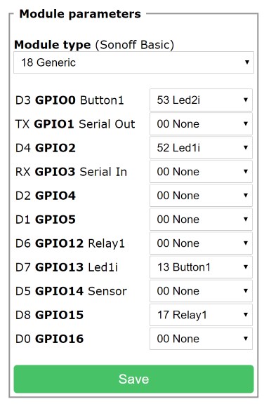
Sonoff devices usually have a bi-colour LED, but just one of the colours can be controlled directly. The other colour is usually tied together with the relay, so it cannot be controlled independently. I think that is the reason why the Sonoff-Tasmota firmware by default controls just Led1 when a single relay is configured. In the configuration above, only the blue LED will be used (tied to GPIO2). But if you prefer the red LED, just change the values for Led1i and Led2i (select Led1i for GPIO0 and Led2i for GPIO2).
Details
If you want to read the detailed project log, you can do so on my GitHub Blog page.