Connection - sergev/linkit-cube-demo GitHub Wiki
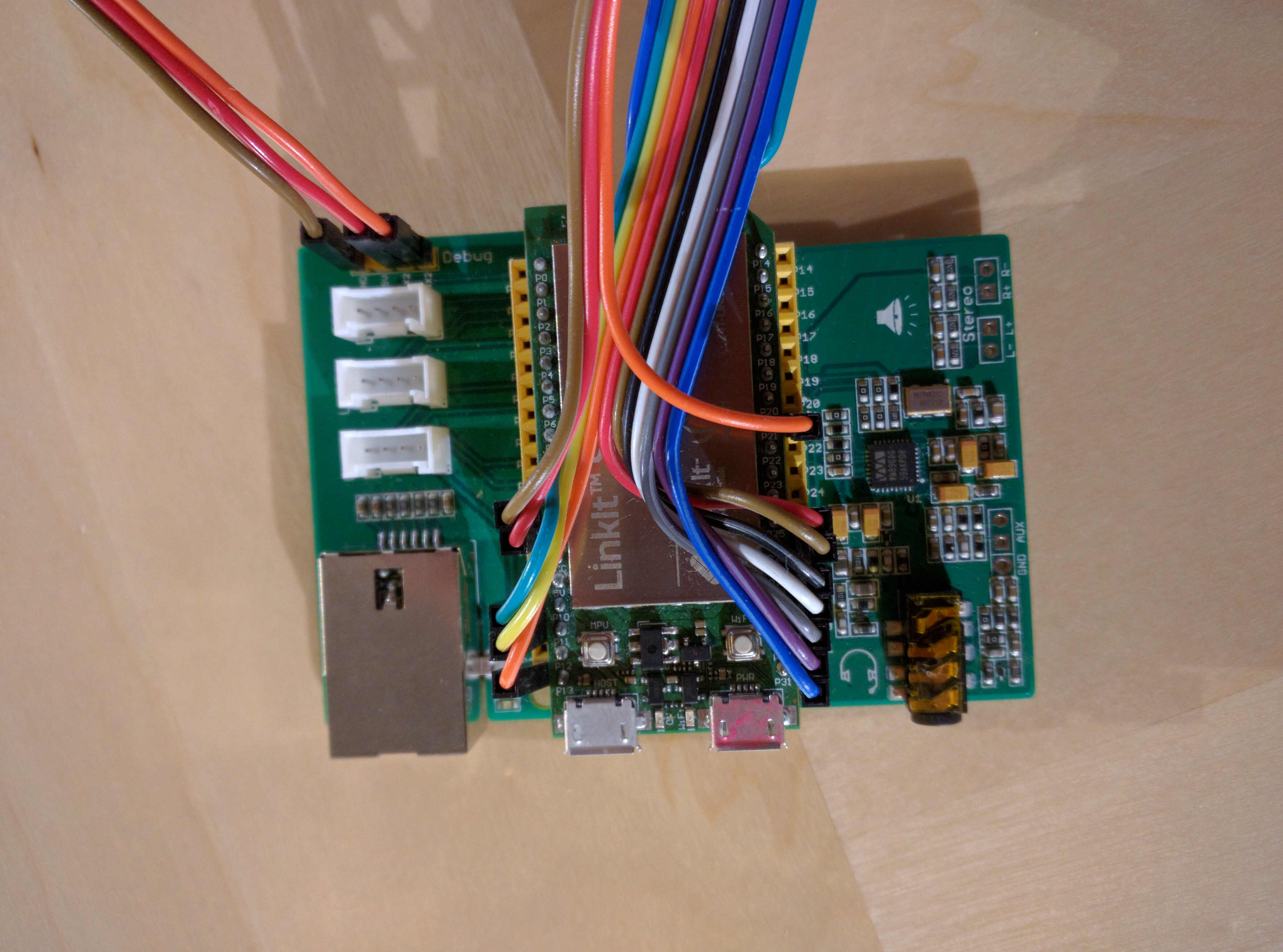
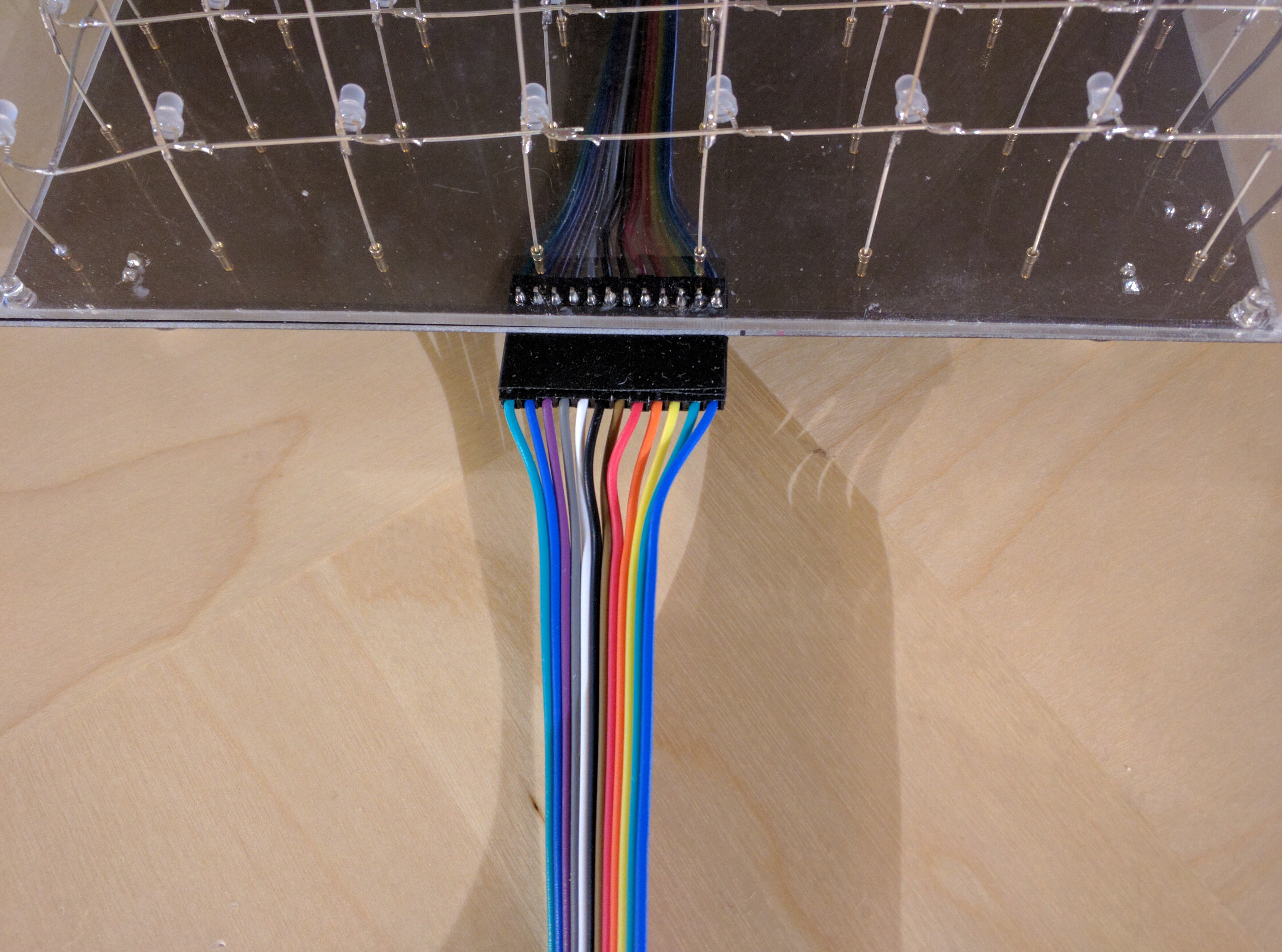
The cube is connected to the Linkit Smart 7688 board, pins P10, P11, P13, P25-P30. Sensor output is attached to the pin P21.
| Cube | Signal | Linkit | MRAA |
|---|---|---|---|
| P1/1 | +5V | 5V | --- |
| P1/2 | Y0 | P10 | gpio2 |
| P1/3 | Y1 | P11 | gpio3 |
| P1/4 | Y2 | P13 | gpio1 |
| P1/5 | Y3 | P25 | gpio6 |
| P1/6 | Y4 | P26 | gpio18 |
| P1/7 | SDI | P27 | gpio19 |
| P1/8 | CLK | P28 | gpio17 |
| P1/9 | /LE | P29 | gpio16 |
| P1/10 | /OE | P30 | gpio15 |
| P1/11 | EXT | P31 | gpio14 |
| P1/12 | GND | GND | --- |
| --- | Sensor | P21 | gpio4 |
Connection to the Linkit board:
            Linkit
        |              |
        |           P21|-- sensor
        |              |
        |              |
  gnd --|GND           |
        |           P25|-- y3
        |           P26|-- y4
  +5v --|5V         P27|-- sdi
   y0 --|P10        P28|-- clk
   y1 --|P11        P29|-- /le
        |           P30|-- /oe
   y2 --|P13        P31|-- ext
        ----------------

Connection to the Cube board:
       Cube
         ------
         |
    GND--|12 - Ground
    EXT--|11 - LED current control
    /OE--|10 - Output enable \
    /LE--| 9 - Latch enable  | shift registers
    CLK--| 8 - Clock         |
    SDI--| 7 - Serial data   /
    Y4 --| 6 - Lower backlight
    Y3 --| 5 - Upper backlight
    Y2 --| 4 \
    Y1 --| 3 | Layer select
    Y0 --| 2 /
    +5V--| 1 - Power
         |
         -------
