1. Hardware Setup Guide - rmullin7286/TFREC-IR-3G GitHub Wiki
Before downloading the necessary software to the RF24 device, you'll have to setup the hardware. First, we'll start with the most straightforward part, the Pi Hub:
This is a pretty straightforward procedure. First, insert your sim card into the bottom of the shield. Make sure it's a full sized card, otherwise it won't fit (the card we used was an AT&T GoPhone card that you can pick up at any AT&T store). Next, align the gpio header on the 3G shield to the header on the Raspberry Pi 3, and press down carefully to attach. That's all the setup needed for this part!
The gpio pins on the shield should exactly match up with the gpio pins of the Raspberry pi. We'll be using some simple GPIO jumper cables to wire the nRF24l01 up. Here's a diagram of the GPIO header of the Raspberry pi 3:
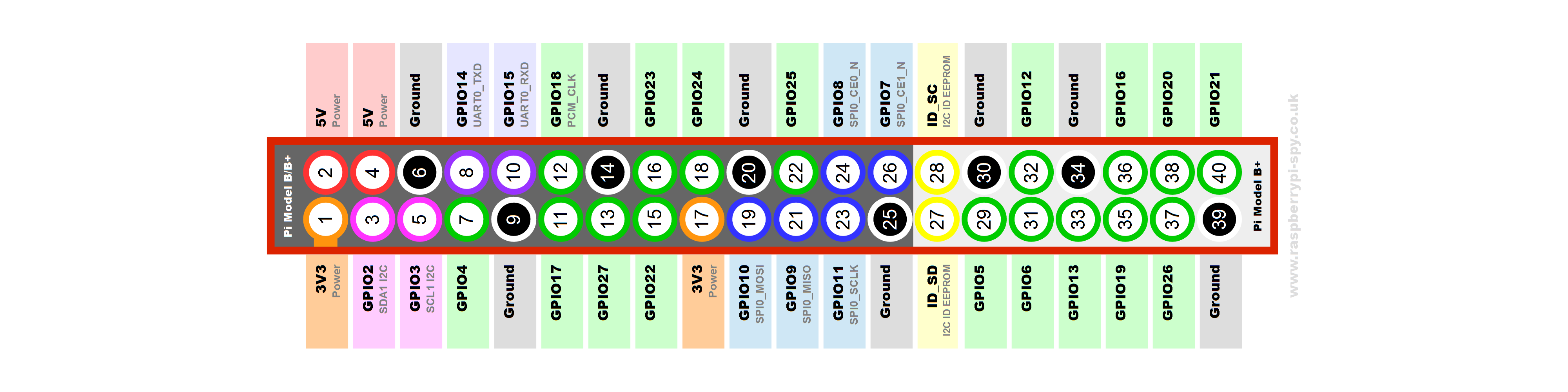
The wires should be wired as follows:
| RF24 | RPi 3 Pin | Pin Number |
|---|---|---|
| V+ | 3.3v | 17 |
| MOSI | MOSI | 19 |
| MISO | MISO | 21 |
| SCK | SCLK | 23 |
| CE | GPIO 25 | 22 |
| CSN | CE0 | 24 |
| GND | GND | 25 |
Once you have everything wired, that should be it for the Pi Hub. Now onto the Pi Sensor:
This will be the trickiest part of the setup as it will require a lot of soldering. Take your time and make sure every joint is properly soldered with no overlapping solders, as the pieces of the shield are extremely compact and close together. Make sure to use Rosin core solder. This is important, as acid core will destroy the circuit board.
Some important things before you begin. Make sure that you purchase the additional stacking header from Adafruit so that the pins will be long enough to connect to both the board and additional jumper wires. This is a crucial part to the setup of the PiSensor. They can be found here.
Follow this link and follow the hardware setup tutorial provided by Adafruit: link
Once you've completed the assembly, attach the LCD Shield to the top of the gpio header similarly to the 3G shield, being careful to line up the pins correctly.
The setup is exactly the same as on the 3G shield, and the pins should line up the same. Follow the setup guide above.
This step will require a bit of soldering, but nowhere near as much as the shield did. To begin, insert the smaller end of the 4 header pins that came with the MLX90614 into the holes at the base of it. Then, carefully solder each part of the header into the holes, making sure none overlap.
Next, wire the MLX90614 to the stacking header of the Adafruit Shield. This is a similar process as the RF24, but the sensor will use the i2c ports. This is a table of how it should be wired:
| MLX90614 | RPi 3 Pin | Pin Number |
|---|---|---|
| Vin | 3.3v | 1 |
| GND | GND | 9 |
| SDA | SDA | 3 |
| SCL | SCL | 5 |
now that you've connected all the wires, your setup is complete! However, it would be good to house the devices in some sort of protective case. We used the Pelican 1050 and drilled holes in the side for the antennae, sensor and LCD plate.