Gremlin is a backplot application that may be used with user interfaces.
For now, this will be a place for notes on particular issues with Gremlin. Hopefully, it will become a comprehensive reference that may be used to create a formal entry into the manual.
hershey.py?
It took me a while to find out why hershey.py has the hershey name. The answer may be here: and . hershey.py has on-board the font data for digits 0-9, -, ., and upper-case letters G, X, Y, Z, U, V, W for labeling axes and the reference frame (for example G54).</td>
Soft Limit Box and Tool Offsets
While using Gremlin, I had instances where the tool would travel across the soft limit lines. If the soft limit values in the .ini file are set to match the machine's firm limits (limit sensors) or hard limits (physical contact with housings or bumpers), the soft limits can provide a safer and more convenient means to deal with running to an end of travel. With the proper settings, the firm or hard limits should never be crossed. This seems to work physically, but not virtually on the display. Analyzing the problem seems to come down to how tool offsets are or are not handled. Here is an example.
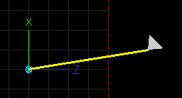
Figure 1
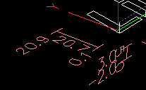
Figure 2
Using gedit on the configuration's .var file, I changed all register values to 0.000000, except for #5220 = 1.000000. This makes all coordinate systems (G53, G54-9) origins at machine zero. I edited the .tbl file to zero all offsets except T1 with an offset of X=-1 and Z=-3. My configuration is for a lathe sim, so other axes don't matter. The configuration's limits are set to [AXIS_0], MIN_LIMIT = -7.0, MAX_LIMIT = 3.0; [AXIS_2], MIN_LIMIT = -8.0, MAX_LIMIT = 2.0. Figure 1 shows the tool and soft limit location (red dotted line) with G49, tool offsets Off. Figure 2 shows G40, tool offsets On. No axis motion happens when switching between G49 and G43, or at least until a position change is called, so in figure 2 the tool should still be within the soft limit. Whether or how to fix this is unresolved.
upload:G43_TLO_On-2.png
Getting closer.
The grid may be harder because draw_grid_lines_permuted calls draw_grid_lines and it looks like a fix to draw_lines will break draw_lines_permuted.
Adding Rear Tool Lathe Features
Some features are needed for the development of a user interface for a lathe using a tool post or changer located behind the spindle. Primarily, the X axis direction has been changed so that the X plus direction points away from the normal operator position. The issues that come from this are:
1.1. How best to flag this configuration so that software applies the proper actions?
The solution so far is to check the .ini file GEOMETRY tag for "-XY". The the code path parallels the code for LATHE=1:
...
class GLCanon(Translated, ArcsToSegmentsMixin):
...
def draw_axes(self, n, letters="XYZ"):
...
if self.is_lathe():
...
def calc_extents(self):
self.min_extents, self.max_extents, self.min_extents_notool, self.max_extents_notool = gcode.calc_extents(self.arcfeed, self.feed, self.traverse)
if self.is_rear_tp_lathe:
# the min/max come in from gcode_calc extents as the negative of the actual value
# if we're displaying a plot for a rear TP lathe
self.min_extents[0] *= (-1)
self.max_extents[0] *= (-1)
...
def draw_axes(self, n, letters="XYZ"):
glNewList(n, GL_COMPILE)
x,y,z,p = 0,1,2,3
s = self.stat
view = self.get_view()
1.2. The Gremlin X axis origin arrow needs to point up instead of down
glcanon.py
...
glColor3f(*self.colors['axis_x'])
glBegin(GL_LINES)
if self.is_rear_tool_post_lathe():glVertex3f(-1.0,0.0,0.0) # Draws line upelse:glVertex3f(1.0,0.0,0.0) # Draws line downglVertex3f(0.0,0.0,0.0)
glEnd()
if view != x:
glPushMatrix()
if self.is_lathe():
<span style=background-color:#ffff88>if self.is_rear_tool_post_lathe():</span>
<span style=background-color:#ffff88>glTranslatef(-1.3, 0, 0) # Draws an X above the line</span>
<span style=background-color:#ffff88>glRotatef(-90, 0, 0, 1)</span>
<span style=background-color:#ffff88>glRotatef(90, 0, 1, 0) # Rotates it to face the viewer</span>
<span style=background-color:#ffff88>else:</span>
<span style=background-color:#ffff88>glTranslatef(1.3, -0.1, 0)</span>
<span style=background-color:#ffff88>glTranslatef(0, 0, -0.1)</span>
<span style=background-color:#ffff88>glRotatef(-90, 0, 1, 0)</span>
<span style=background-color:#ffff88>glRotatef(90, 1, 0, 0)</span>
<span style=background-color:#ffff88>glTranslatef(0.1, 0, 0)</span>
...
1.3. The tool tip image is on the wrong side of the tool's control point
Study of how tool orientation 9 is drawn
glcanon.py
...
        if orientation == 9:
            glBegin(GL_TRIANGLE_FAN)
            for i in range(37):  # 10 degree increments in 360
                t = i * math.pi / 18  # angle in Radians
                glVertex3f(radius * math.cos(t), 0.0, radius * math.sin(t))
            glEnd()
...
This image shows a circle using the same GL_TRIANGLE_FAN method except at 30 degree increments.
upload:to9_fan-1.png
This sheds light on the other tool orientations which prompts a proper fix.
...
The fix was easier than I thought. I copied the existing orientation map and swapped settings for 2 and 3, 6 and 8, and 1 and 4. Easy peasy.
### glcanon.py
...
if orientation == 9:
glBegin(GL_TRIANGLE_FAN)
for i in range(37): # 10 degree increments in 360
t = i * math.pi / 18 # angle in Radians
glVertex3f(radius * math.cos(t), 0.0, radius * math.sin(t))
glEnd()
else:
...
if self.get_show_limits():
glLineWidth(1)
glColor3f(1.0,0.0,0.0)
glLineStipple(1, 0x1111)
glEnable(GL_LINE_STIPPLE)
glBegin(GL_LINES)
<span style=background-color:#ffff88>if self.is_rear_tool_post_lathe():</span>
<span style=background-color:#ffff88>x_dir = -1</span>
<span style=background-color:#ffff88>else:</span>
<span style=background-color:#ffff88>x_dir = 1</span>
# Draw 3d box at soft limits for X, Y, and Z axes
glVertex3f(<span style=background-color:#ffff88>x_dir *</span> machine_limit_min[0], machine_limit_min[1], machine_limit_max[2])
glVertex3f(<span style=background-color:#ffff88>x_dir *</span> machine_limit_min[0], machine_limit_min[1], machine_limit_min[2])
glVertex3f(<span style=background-color:#ffff88>x_dir *</span> machine_limit_min[0], machine_limit_min[1], machine_limit_min[2])
glVertex3f(<span style=background-color:#ffff88>x_dir *</span> machine_limit_min[0], machine_limit_max[1], machine_limit_min[2])
...
fix for grid
glcanon.py
...
def draw_grid_lines(self, space, (ox, oy), (dx, dy), lim_min, lim_max,
inverse_permutation):
# draw a series of line segments of the form
# dx(x-ox) + dy(y-oy) + k*space = 0
# for integers k that intersect the AABB [lim_min, lim_max]
lim_pts = [
(lim_min[0], lim_min[1]),
...
if self.is_rear_tool_post_lathe():x_dir = -1else:x_dir = 1
...
class GlCanonDraw:
colors = {
'traverse': (0.30, 0.50, 0.50),
...
def redraw(self):
s = self.stat
s.poll()
...
if self.get_show_live_plot() or self.get_show_program():
alist = self.dlist(('axes', self.get_view()), gen=self.draw_axes)
glPushMatrix()
if self.get_show_relative() and (s.g5x_offset[0] or s.g5x_offset[1] or s.g5x_offset[2] or
s.g92_offset[0] or s.g92_offset[1] or s.g92_offset[2] or
s.rotation_xy):
olist = self.dlist('draw_small_origin',
gen=self.draw_small_origin)
glCallList(olist)
g5x_offset = self.to_internal_units(s.g5x_offset)[:3]
<span style=background-color:#ffff88>if self.is_rear_tool_post_lathe():</span>
<span style=background-color:#ffff88>g5x_offset[0] *= -1</span>
g92_offset = self.to_internal_units(s.g92_offset)[:3]
 It took me a while to find out why hershey.py has the hershey name. The answer may be here: and . hershey.py has on-board the font data for digits 0-9, -, ., and upper-case letters G, X, Y, Z, U, V, W for labeling axes and the reference frame (for example G54).</td>