ContributedComponents - rmu75/linuxcnc-wiki GitHub Wiki
This page is a place for users to contribute HAL components and other LinuxCNC/HAL-related information in the hope that they will be useful to others. See also: ContributedHalFiles
Follow the BasicSteps so that you can edit the wiki. Use the "Upload" link at the top of this page to upload your component as a .c, .py, .comp, or .tar.gz file. Then add a new section to this page with a short description of your component and a link to the file you uploaded.
First, install the linuxcnc-dev (sudo apt-get install linuxcnc-dev) and build-essential packages (sudo apt-get install build-essential). If the component does not provide specific installation instructions, then try these general instructions:
*If a file called 'Makefile' is included: *make && sudo make install *Userspace component ending in .py: chmod 755 component.py && sudo cp component.py /usr/local/bin/component
*Userspace component ending in .comp or .c: *LinuxCNC versions 2.6.n and earlier: *sudo comp --install --userspace component.comp *LinuxCNC versions 2.7.0 onwards *sudo halcompile --install --userspace component.comp *Realtime component ending in .comp or .c (including kinematics files) *LinuxCNC versions 2.6.n and earlier: *sudo comp --install component.comp *LinuxCNC versions 2.7.0 onwards: *sudo halcompile --install component.comp (versions 2.7 and later)
Clearly label each submission with its license. Submissions hosted on linuxcnc.org must be as free or freer than </nowiki>LinuxCNC</nowiki>. This means approximately that they have a license accepted under the [Debian Free Software Guidelines]. GPL and LGPL are two examples of permitted licenses. "Free For Noncommercial Use" is an example of a non-permitted license.
*For all types of file, include the standard license block indicated by the license being used. *For ".c" components, also specify MODULE_LICENSE("...");. *For ".comp" components compatible with LinuxCNC (EMC2.1 and later), also specify MODULE_LICENSE("...");. *For ".comp" components compatible with LinuxCNC (EMC2.2 and later), also specify license "...";
upload:emc2_ethercat.tar.gz.tar
License: GPL
This component uses the IGH [EtherCAT Master library] to talk to a EtherCAT connected [DigIO Terminal]. A Description can be found in this wiki at etherlab
upload:candcnc_ubob.tar.bz2
License: GPL
There are two components in this file and a sample config for using the [CandCNC] UBOB breakout board. The config is currently missing some important features such as using the external E-stop signal, but will show the basics needed to set up these breakout boards. The components drive the multiplexed inputs and the serialized outputs.
Component to convert step and direction signals from a step generator to current intensity for a dac that drives the 7i32 hardware.
currently does 1/2 and 1/8 micro stepping
Possible to compensate for angular error by changing the intensity ramp data
I haven't used this to move anything important -it is experimental- improve it!
Chris Morley c/o [email protected]
upload:mesa7i32driver.comp
Component controls 8 station ATC fitted to Boxford 240, 160 and 125
Works on degrees of movement, with ATC defined as rotary axis, so does not require index sensors.
Should be able to be adapted for any lathe using a 'rotate past pawl and reverse to lock' methodology.
Amount of rotation configurable for fine tuning, see README and notes in .comp file for details
upload:Boxford.tar.gz
License: GPL
Component controls 8 station ATC fitted to Orac lathe
Reads greyscale optical disc and compares to 3 sensor truth table to determine tool position
See header of comp file for full details and specimen hal file linkage
upload:oracchanger.comp
Licence: GPL
Component controls 8 station ATC fitted to Emco lathe
Reads greyscale optical disc and compares to 4 sensor truth table to determine tool position
Sample .hal file and connection pinout in file also
upload:emcochanger.txt
upload:EmcoTurnConfigs.zip
Licence: GPL
Component controls 8 station ATC fitted to Emco lathe
Schematic, PCB etc plus ino and comp files included - Updated toolerator.ino (on 083115) to improve turret indexing
upload:toolerator.zip
upload:mstcPCBFiles.zip
Licence: GPL
The tool changer component homes the carousel once the mill has been homed, to establish where tool 1 index is
and from that which tool is in the spindle.
Thereafter a M6Tn command prompts the removal of the current tool from the spindle, rotation of the carousel to the tool
requested and the insertion of that tool in the spindle.
The component uses a modified version of ioControl.cc to automatically update the toolnumber held by linuxcnc and displayed in Axis
This realistically makes the component most easily used within a RIP environment where the new iocontrol can be built in the source tree
Included in the zip are cncbashers config files to demonstrate the connections required in HAL.
The main tuning considerations, in common with many components interfacing with electro-mechanical / pneumatic tool changers,
are appropriate delays to allow relays to open, rams to move to their full extent etc.
The figures in the config files are for cncbashers own machine in conjunction with Mesa boards
If software stepping were used and a normal BOB, the delays may require to be longer.
These can be set using the 3 param pins, shortdelay, longdelay and extralongdelay
upload:triac_toolchanger.zip
The zip contains files for the complete system put together by Thomas Kamsker to control the ATC on his shop Bridgeport 412.
The solution includes spindle orientation, re-mapping of M6, fitting of carousel indexes and much more
It uses a GM card, which unless your machine has one, will not be directly usable as is, but is a good learning source
for an involved tool changing solution.
Web pages detailing the project are here
www.tkamsker.at/web/pub/bridgeport-412-retrofit
All the component, remap, macro and config files are here
upload:Bridgeport412-ATC.zip
upload:millkins.c
License: GPL
Info from a recent IRC discussion
compile & install millkins.c as per instructions at top of page
change 'loadrt trivkins' to 'loadrt millkins' in hal file
add a 'setp millkins.skew #.###' to set the amount of correction to apply
'#.### is unitless and derived from mm/mm of skew or in/in of skew
- millkins_xyz.c - trivial kinematics extended by XY, XZ, and YZ skew correction
A variation of the original millkins file. Instead of just being able to correct one axis due to mechanical issues (skew), you can now adjust the Y axis as before, but with the addition of Z axis correction. This is used in case your Z axis does not move perpendicular to the XY plane (imagine drilling a hole with the drill straight up and down while moving at an angle downwards). This will not correct issues with the spindle not being perpendicular to your XY plane. It only corrects your Z axis not going straight up and down in relation to the XY plane.
Adjustments are for the Y, XZ and YZ planes. You will have 3 seperate entries in your HAL file. See below.
How to compile and install a component
First, install the emc2-dev (sudo apt-get install emc2-dev) and build-essential packages (sudo apt-get install build-essential).
Compile & install millkins_xyz.c: sudo comp --install ~/linuxcnc/configs/my-mill/millkins_xyz.c
Change 'loadrt trivkins' to 'loadrt millkins_xyz' in hal file
Add a 'setp millkins_xyz.skew_y #.###' to set the amount of correction to apply in "Y"
Add a 'setp millkins_xyz.skew_xz #.###' to set the amount of correction to apply in "XZ plane"
Add a 'setp millkins_xyz.skew_yz #.###' to set the amount of correction to apply in "YZ plane"
'#.### is unitless and derived from mm/mm of skew or in/in of skew
upload:skew%20instructions.txt
upload:millkins_xyz.c
License: GPL
upload:XYZAC.tar.gz
Two rotary joints have been added: A around x-axis and C around z-axis. They may have offsets Y-offset and Z-offset. A vismach gui called XYZACgui is included to show actual machine movements. A sample Gcode file is included.
See README file for instructions to install and run a simulation of the Flange.ngc file
upload:linear8.comp
License: GPL
This component is useful for obtaining a closer relationship between S- speed commands and spindle speed when the spindle's response to a PWM input is nonlinear.
upload:prbs.c
upload:prbs-fixed.c (the original above lacked a call to hal_ready()).
License: GPL
prbs.c is an HAL module for generating the PRBS (Pseudo-Random Binary Sequence) signal. This signal is basically used as an excitation signal at the reference input. PRBS is used because of its rich frequency spectrum. This "prbs.c" is based on the algorithm provided in the following book,
Landau, Digital Control Systems, http://landau-bookic.lag.ensieg.inpg.fr/english/index.htm
It has been used to identify to the axial dynamics in closed loop ( the book site provide the tools). With the model, it is possible to design advanced controllers rather than PID controllers for the axial servo drive. Thus, the positioning and tracking accuracy of the servo drive can be improved, the final accuracy of the parts can also be improved. But much work needs to be done yet.
Useful for torque-mode servo amplifiers that don't respond to DAC output in some interval around zero.
http://www.anderswallin.net/2008/04/idb-inverse-deadband-component-for-emc2/
useful for setting things like coolant from a momentary-on pushbutton.
http://www.anderswallin.net/2008/04/toggle2nist/
Useful for tool changers, especially carousels that wrap, such as when the last tool wraps to tool one, or tool one to the last.
In .hal use:
"
loadrt modmath mod_dir=N
...
addf mod-dir.0 servo-thread
...
addf mod-dir.N servo-thread
This will create these pins:
"
halcmd show pin mod-dir
Component Pins:
Owner Type Dir Value Name
8 s32 IN 0 mod-dir.0.actual
8 s32 IN 0 mod-dir.0.desired
8 bit OUT FALSE mod-dir.0.down
8 s32 I/O 15 mod-dir.0.max-num
8 s32 I/O 0 mod-dir.0.min-num
8 bit OUT TRUE mod-dir.0.on-target
8 bit OUT FALSE mod-dir.0.up
8 bit I/O TRUE mod-dir.0.wrap
"
"up", "down", and "on_target" are bit outputs that tell whether to go up, down, or nowhere. Exactly one of those will be "1" at any time.
"actual" and "desired" are integer inputs that tell where the carousel is and where you want it, respectively.
"max" and "min" are the highest and lowest tool slot numbers. Note that tool numbers actually start with 1, so you may need to fiddle with the desired/actual values and/or the requested slot output to the tool changer) to get the tool you really want.
"wrap" is a bit input which you probably want to set true, if the changer is a carousel. If set true, then it's assumed that max is next to min and you can get from min to max by going "back" one and wrapping around.
(modmath end KW 2010/03/10)
upload:enshu.comp
upload:sinesweep.comp
Component to generate a sine sweep. This may be used to find mechanical resonances in the LinuxCNC-controlled machine so they can be actively dampened. Example HAL snippets to use this:
 # Load component, setup parameters. Be careful with the amplitude; a resonating machine
 loadrt sinesweep
 addf sinesweep.0 servo-thread
 setp sinesweep.0.start-freq 10.0
 setp sinesweep.0.end-freq 500.0
 setp sinesweep.0.sweep-duration 30.0
 setp sinesweep.0.log-sweep 1
 setp sinesweep.0.amplitude 1.0

 # inject sine signal into a servo loop. Injecting it as torque or current directly into a servo amp would be great, but velocity or position works too.
 net sweep-inject sinesweep.0.output => servo_pid.bias
When the component is setup, start halscope and add traces on sinesweep.0.start, sinesweep.0.curr-freq and the velocity signal coming from the servo encoder. Setup triggering on sinesweep.0.start rising edge. Now, go to a terminal and execute the command 'halcmd setp sinesweep.0.start 1'. Halscope triggers and plots the response for you. The locations in the plot where there are significant peaks in the velocity signal from the servo are likely resonances. Dampening of these resonances can be done either mechanically or partially electrically by using 'biquad' components in notch mode.
A more powerful method of plotting and evaluating the results of a sine sweep would be to use 'sampler' and 'halsampler' to log the data to a file, and parse that file using your favorite data processing application (MatLab, Octave, Excel, Calc, etc.)
upload:whitenoise.comp
Component to generate white noise. Useful for finding system resonances or to reduce servo hunting by adding a tiny bit of noise to the servo signal.
"Arduino is an open-source electronics prototyping platform based on flexible, easy-to-use hardware and software". The Arduino diecimila board offers 6 ADC channels, 6 PWM channels, and 6 digital I/O channels. 'arduino' is a HAL driver and associated firmware for this device.
See http://axis.unpy.net/01198594294 for more information and to download the driver.
hidcomp provides an interface to USB HID (Human Interface Device) devices. This includes joysticks, games pads, multimedia controlers, etc. A GUI program is used locate, test and configure the devices.
See http://www.franksworkshop.com.au/EMC/hidcomp/hidcomp.htm for more information and to download the applications.
vfs11_vfd controls an VF-S11 through a serial Modbus connection. See the man page at http://mah.priv.at/src/vfs11_vfd/vfs11_vfd.html .
The VF-S11 doesnt have a standard RS-232 port - here is a little converter to connect a VF-S11 to an RS-232 port [upload:vfs11-rs232.pdf], based on a note from Toshiba support: [upload:VFS11-RJ45_e.pdf]
The current stable version can be found at http://git.mah.priv.at/gitweb/vfs11-vfd.git .
I also wrote a utility to explore Modbus clients, which helped to write the vfs11-vfd driver. It is available at: http://git.mah.priv.at/gitweb/modio.git
Update: vfs11_vfd is now integrated into master. see src/hal/user_comps/vfs11_vfd .
This is an starting point for folks who would want a modbus driver for multiple identical modbus clients (in this case, modbus-capable servo amplififers):
http://git.mah.priv.at/gitweb/emc2-dev.git/shortlog/refs/heads/modbus-generic-driver
Les says:
This driver <http://www.shootspammers.org.uk/modbus.zip> I wrote some time back will work with multiple modbus clients. They can be different or identical. You can even use multiple ports. All parameters are configured via an ini file.
upload:modbus.zip
This is a Modbus driver for An Altivar ATV71 VFD contributed by Martin Kaplan.
See http://git.mah.priv.at/gitweb/emc2-dev.git/shortlog/refs/heads/altivar-vfd-comp .
Controls a Danfoss VLT5000 series VFD through an RS485 link using the Danfoss FC Protocol.
Documentation:
Compile the documentation using 'comp --document vlt5000_vfd.comp'.
The resulting manpage (vlt5000_vfd.9) can be viewed with 'man ./vlt5000_vfd.9' or copied to a standard location.
Installation: comp --install vlt5000_vfd.comp
Usage: loadusr -W vlt5000_vfd --device=<yourserialport>
This component is tested using a Danfoss VLT5008 VFD, an FTDI USB-COM485-PLUS1 USB->RS485 converter module and LinuxCNC 2.7.0~pre
The basic functionality of starting/stopping the motor and setting the reference speed probably also works on other VLT drives. Extended functionality such as reading the actual motor power probably doesn't.
If you use this component successfully on other VLT drives, please let me know (dabit weird A character icecoldcomputing littlepoint com)
upload:vlt5000_vfd.comp
This is HAL component for USB thermometer Microdia TEMPer1V1.2
upload:temper1.tar.gz
This HAL component drives 74LS595 and 74LS597 latching shift registers (or equivalent) for a cheap and easy way to add I/O lines to your port. The shift registers can be daisy-chained together to provide pins in multiples of 8. As currently configured, the component will create 16 input and 16 output lines, requiring only 3 output and 1 input pin on your existing port.
For a complete write-up, see http://www.shafferhouse.org/linuxcnc/LinuxCNCShiftRegisters.pdf
upload:lsrio16.comp
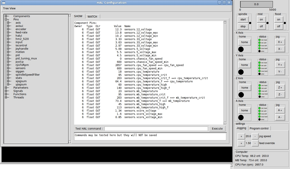
This is a python component that will extract all the sensor readings for the motherboard/CPU/fan and make them available as HAL pin values. These Temperature, RPM, Voltage readings can then be displayed in a pyVCP, or used in any other interesting manor. When the script starts up, it will parse and create the various output pin values on the fly based on what it finds in the output from the 'sensors' command.
https://forum.linuxcnc.org/media/kunena//attachments/legacy/files/sensors.txt
https://forum.linuxcnc.org/media/kunena/attachments/legacy/images/sensors.jpg
This userspace component will generate up to 1000 (0 - 999) pairs of IN pins and OUT pins of each, of types float, s32 and bit.
The OUT pins can be overwritten by reading from a file, enabling components or widgets attached to those pins to be initialised to known or saved values.
The IN pins can be connected to any suitable component pin or widget pin The values received at the IN pins can be saved to file making settings persistent between shutdowns.
This comes into its own if you use my amended pyvcp_widgets http://www.linuxcnc.org/index.php/english/forum/38-general-linuxcnc-questions/26427-setting-initval-of-a-spinbox-in-hal?start=27
Then you can link say the hal-pin of a spinbox to paramsaver.invalueF-00 and the new param-pin of the spinbox to paramsaver.outvalueF-00
Set paramsaver.writetrigger to true and create a file
Set paramsaver.readtrigger to true and the value will be inserted back into the spinbox.
Commandline switches:-
loadusr -W paramsaver f=NNN s=NNN b=NNN filename=xxxxxxx onstart=0/1 onexit=0/1
See man page (paramsaver.9) in zip for full details
upload:paramsaver6.zip
Licence: GPL
Upload a screenshot of the ladder logic rung(s) and an explanation of the inputs and outputs. and add the .clp file
also see: ClassicLadderExamples for other examples
A testpanel and script for the m5i20 using hostmot4 driver.
[upload:testpanel.tar.gz]