Batteries - rittme/nrfmicro GitHub Wiki
Chargeable batteries
301230
I'm using 301230 (301230 means 3.0 x 12 x 30 mm) Li-Po batteries, they sit flush and fit snugly between two 4.5mm tall machine pin sockets (read the Sockets article about the hotswap headers).
- https://www.aliexpress.com/item/32831998939.html 301230 batteries, 80(110?) mAh, $8.81 for 10 pcs (confirmed to work)
- https://www.aliexpress.com/item/4000336487717.html (got these ones, took about 2 months, good seller)
Use RAW and GND or B+ and B- pins for the battery (those pairs of pins are internally connected so they are essentially the same). Avoid reverse polarity (charger ICs usually fry first)!
Note that a few keyboards have RAW and VCC pins connected together (namely Helix and Gherkin), and will kill the controller (RAW pin is for the charger only). You may just not solder RAW pin to the keyboard as a workaround.
Video
- https://youtu.be/CsANtp6a3YU?t=166 (sockets are 3.5mm PBS, see Sockets)

Capacity
Latest batches come blank without printing but with 80 mAh sticker on the bag. I'm not sure if they are 110 mAh or 80 mAh (probably the latter, they are pretty small, but all the 301230 batteries, even declared as 110 mAh look precisely the same). New batch vs old batch, same seller:

Charging
Charging current is set by the PROG pull-down resistor, Icharge = 1000V/Rprog. Safe charging current in mA roughly equals battery capacity in mAh (1C rate) and default batteries are 100 mAh so charging current is 100 mA and PROG resistor is 10K.
If you want 2500 mAh battery, mind that charging it at 100 mA would take 25 hours. Charging current is also limited by the USB port (USB 2.0 is 500 mA) and the charger (TP4054/MCP73831 both rated for about 500 mA), so the best you can do is replace 10K resistor with a 2K resistor for 500 mAh. Charging still takes at least 5 hours (2500 mA / 500 mA).
Software control in nRFMicro 1.3 (PROG resistor wired to the GPIO pin) adds more options with 13K internal pull-down:
- 10K resistor (100 mAh default) with 13K pull-down option: 1000/(10+13) ~= 43 mA (for LIR2032 coin cell batteries)
- 2K resistor (500 mAh default) with 13K pull-down option: 1000/(2+13) ~= 67 mA (for small Li-Po batteries)
nrf_gpio_cfg_input(PROG_PIN, NRF_GPIO_PIN_NOPULL); // charger disabled (PROG pin set to float)
nrf_gpio_cfg_output(PROG_PIN); nrf_gpio_pin_write(PROG_PIN, 0); // just the onboard resistor
nrf_gpio_cfg_input(PROG_PIN, NRF_GPIO_PIN_PULLDOWN); // onboard resistor and 13K internal pulldown

18650
If you're planning to use 18650 batteries, mind that nRFMicro/nicenano/bluemicro/whatever don't have discharge protection (Li-Po packs have it, but most 18650s don't).
You can control it it firmware though, and discharge rate in BLE is pretty low. You can also try using 3-rd party charger boards with discharge protection like 03962A and solder the to the USB power lines but that wouldn't be easy to solder and route.
- https://www.aliexpress.com/wholesale?SearchText=03962A (search for 03962A chargers on Aliexpress)
There are 18650s with discharge protection but they are a little bit larger and more expensive. You will also need to replace PROG resistor on the nRFMicro from 10K to 2K to boost charging current to 500 mA (100 mA just takes 5 times longer to charge, e.g. 100 mA charger takes 35 hours to charge the 3500 mAh battery, 500 mA charger takes 7 hours). Those batteries are about 5 mm longer and have a side wire (may be hidden).
- https://www.aliexpress.com/item/32807032859.html (NCR18650B batteries with discharge protection)

LIR2032
Those coin cells don't have over-discharge protection either, this is the main concern with the coin cell batteries. Mind that nominal capacity is just 40 mAh, while regular non-chargeable CR2032 cells offer 250 mAh. Nominal charging current is 35 mA, they probably can be charged at 100 mA (2.8C rate) but you may replace the PROG resistor to 27K (1000/27 ~ 37 mA) for safety.
- LIR2032 battery backpack: https://store.jpconstantineau.com/#/item/LIR2032 (holders are Keystone 1058)
The battery pack is open-source, see https://github.com/jpconstantineau/NRF52-Board/tree/master/BatteryPack it doesn't add much to the charger except the battery holder and the ON/OFF switch but it still might be handy. It also adds the physical reset button.

03962A Charger
Neither TP4054 nor BQ24072 (introduced in nicenano V2) provide overdischarge protection. BQ24072 provides short-circuit protection but not the overdischarge protection. The discharge limit for the unprotected 18650s (or coin cells) is 2.5V. If they go lower it causes permanent damage to the cell. Even worse, if you don't realize you severely overdischarged a Li-Ion cell and try to recharge it, there's a significant chance of thermal runaway (explosion). Li-Po packs are safe but not the coin cells.
The 03962A schematic provides both overcharge and overdischarge protection with DW01A, R3 is RProg (charging current):

- Overdischarge protection IC is DW01A: https://www.best-microcontroller-projects.com/dw01a.html
You can use 03962A charger for LIR2032s either, but you must to replace RProg. TP4056 current is calculated differently from TP4054, it's Icharge = 1200V/Rprog, so closest R is 34K (you can buy 33K) at 35 mA.

Cellphone Batteries
You can use Li-Po/Li-Ion batteries from the old phones, they have about the same chemistry as Li-Po packs and the same protection circuit. Just solder to + and - terminals, ignore the third one (it's usually 1-wire interface for the battery info). You can't use NiMh/NiCd batteries because they are not compatible with the Li-Po charger. All newer batteries (e.g. starting from Nokia BL 5C/6C) should work.

Non-chargeable batteries
You also could use non-chargeable batteries, setting PROG to float (disconnected) is the official way of disabling the charger. Some nRFMicro revisions can disable the charger in software (e.g. nRFMicro 1.3), other versions need desoldering the PROG resistor (10K).
Misc
Measuring battery capacity
You can measure either battery voltage with voltage divider or both battery current and voltage (also temperature) with fuel gauges.
Note that nRFMicro 1.1 uses 10K/13K divider (external pull up/internal pull-down). That'd give us about 4.2 V / 26 K = 0.16 mA leak (that's quite a lot), however it can be controlled from firmware (internal pull down can be turned off). Also the battery can be disconnected through the physical on/off switch. nRFMicro 1.2 introduces 800K/2M battery divider so the leak is almost non-existent (1.5 uA, or 0.0015 mA).
Voltage divider
There are two versions of the battery voltage measuring circuit pointed out here:
To reduce the leakage current through the voltage divider to the minimum, we want the total resistance to be as high as possible. Therefore, we choose R1 to be 800 KΩ. This is the maximum source resistance we can have if we use an acquisition time of 40 us, see here https://infocenter.nordicsemi.com/index.jsp?topic=%2Fcom.nordic.infocenter.nrf52832.ps.v1.1%2Fsaadc.html
We also want R2 to be large. R2 should be chosen such that the input voltage does not exceed Vdd when the battery is full (4.2 V). In this example Vdd is 3.3 V, so we choose R2 to be 2 MΩ which will give 3 V at AIN when battery is 4.2 V. With a gain of 1/5 we can use the internal reference at 0.6 V.
The leakage current with this configuration will be:
4.2 V / 2.8 MΩ = 1.5 uA If you are using lower Vdd, R2 will have to be smaller and the leakage current will increase.
Usable ADC resolution
If we assume that the voltage range of the Lithium battery is 2.7 V - 4.2 V, i.e. 2.7 V when empty and 4.2 V when fully charged, then the voltage range on the ADC AIN input pin is:
- Maximum voltage: 4.2 V * (2 M/(0.8 M+2 M)) = 3 V
- Minimum voltage: 2.7 V * (2 M/(0.8 M+2 M)) = 1.93 V
- ADC value at 4.2 V – 12 bit setup: 3 V * (1/5) / 0.6 V * 4095 = 4095
- ADC value at 2.7 V - 12 bit setup: 1.93 V * (1/5) / 0.6 V * 4095 = 2634
- Usable ADC resolution - 12 bit setup: 4095 - 2634 = 1461
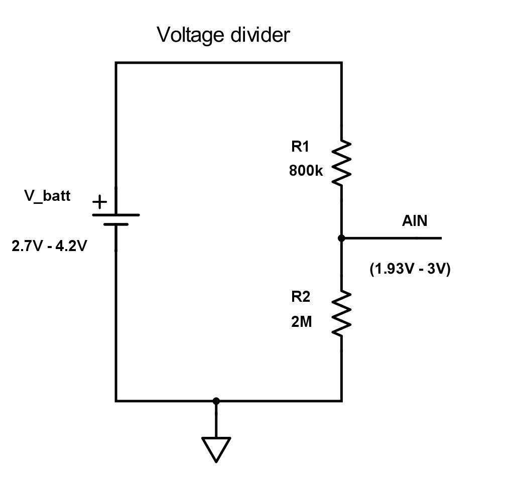
(Leakage current 4.2 V / 2.8 MΩ = 1.5 uA)
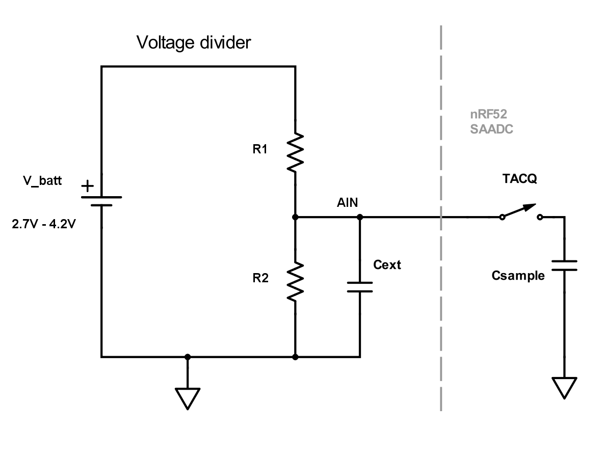
R1=4M, R2=10M, Cext=10nF, Csample=2.5pf, leakage current 4.2V / (10MOhm + 4MOhm) = 300nA
You can also try using a pfet controlled by a mcu pin with a capacitor in series, that way there's no leakage, apart from the iq from the pfet (via @gms):

Fuel gauge
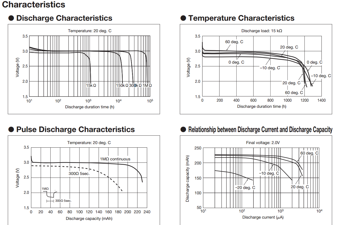
- There are things like STC3100 with a built in battery gauge (current in/current out over time), but it's controlled via I2C, so that might be too complicated and it's pretty expensive overall: STC3100 costs $1-$1.5. Current gives way more accurate measurement in terms of battery capacity though, voltage is superflat almost the entire discharge time:
-
There are also other dedicated ICs, like MAX17055 (The MAX17055 is a low 7μA operating current fuel gauge which implements Maxim ModelGauge™ m5 EZ algorithm. The MAX17055 provides precision measurements of current, voltage, and temperature). It costs $2 on lcsc.
-
There is also LC709203 used in BluePhage, this is the only one supported by Circuitpyhon, so recommended. Example wiring (note those fuel gauges do NOT include battery charging ICs):

Note that the nRF52 chips have a temperature sensor embedded. We don't call it in our keyboard software but it would be relatively easy to add. Perhaps a bit more difficult than just adding a library for the DHT temp sensor:
Discharge rates
More realistic charge for RC batteries (from http://learningrc.com/lipo-battery):

Disabling the charger
It's possible to monitor battery voltage accurately while charging. You'd need to disable the charger to see the lipo's actual value.
you will need to occasionally stop the charge current to read the battery voltage at open load. This will help you correctly find the actual State Of Charge (SOC)
Without disabling the charger you get somewhat average voltage between 4.2V and the actual battery voltage so you have to account for it.
Chargers such as MCP73831 or TP4054 can be disabled by setting PROG pin to float (this is official documented way of disabling those chargers). Disabling a charger in software is super easy. Just cut the line after the PROG resistor and put a digital pin there. Set it to 0 to enable, set it to float (input with no-pull or default high-z state) to disable.

It's probably even better when the charger is disabled by default, people using non-chargeable batteries all the time, getting a Li-Po is somewhat more complicated.
Another possible solution could be using MCP73811, which has enable pin (CE) and also can digitally switch between 85 mA and 450 mA, that could be useful for handling different batteries (recommended charging current is at most 1x capacity, e.g. 100 mA for 100 mAh battery).
WARNING: MCP73811 is not MCP73831 compatible, the pinout is different, they work differently!
- http://ww1.microchip.com/downloads/en/DeviceDoc/22036b.pdf (MCP73811 datasheet)
- http://ww1.microchip.com/downloads/en/DeviceDoc/20001984g.pdf (MCP73831 datasheet)

MCP73811
-
3.1 Charge Enable Input (CE) A logic High enables battery charging. A logic Low disables battery charging. The charge enable input is compatible with 1.8V logic.
-
3.5 Current Regulation Set (PROG) For the MCP73811, the current regulation set input (PROG) functions as a digital input selection. A logic Low selects a 85 mA charge current; a logic High selects a 450 mA charge current.
Sadly MCP73811 are kind of rare and expensive, the cheapest I could find cost $0.50 a piece:
- https://www.aliexpress.com/item/32977687533.html (MCP73811T-420IOT, $10 for 20 pcs)
Other chargers
-
There's also MCP73812, it has CE pin but doesn't have digital power selector (charging current is Rprog-controlled).
-
There's a whole bunch of SOT-23-5 chargers it seems (TP4054, TP4055, TP4065), all SOT-23-5 all MCP73831 clones. Using MCP73831 at the time probably was a bad decision, it's just that Adafruit feather uses it. It's worth to go with TP4054 next time. The cheapest substitute with the english datasheet is LN2054Y42AMR.
-
You could try to get rid of the battery measuring voltage divider altogether (minus 2 resistors) and use internal input VDDHDIV5 of SAADC (still needs 10 uH inductor for the high voltage mode). Sadly, without the divider you can't measure the battery when the USB is on because power selector switches to USB.
-
Nicenano V2 and Mikoto use BQ24075 in VQFN-16 package.
Battery Life
QMK
Author of https://github.com/sekigon-gonnoc/BLE-Micro-Pro commented on battery life on twitter:
It highly depends on configuration and connection parameters which determine delay. With default parameters in master-slave configuration, current is 300uA while typing, <100uA in standby (keyboard is connecting but you don't type), and <1uA in deep-sleep mode (no connection).
So at 0.2mA average it discharges a 110 mAh battery in about 110/0.2 = 550 hours (22 days). With 2500 mAh battery that would be about 2500/0.2 = 12500 hours (520 days, 1.4 years).
Bluemicro
Check out this video by jpconstantineau (he got 1.2-1.6 mA average while typing): https://youtu.be/bMEYIw4oQrw
When powered up, the keyboard uses an average current between 1.2 mA and 1.6 mA. The current varies depending on whether the keyboard is connected to a computer, broadcasts BLE and also depends on keys being pressed or not.
The high current peaks you see on the trace are when the radio of the nrf52 is broadcasting. What has the most impact on current between the peaks is whether the processor in the nrf52 goes in low power mode until the next timer interrupt. If the processor never goes in low power mode, the average current of 1.2-1.5 mA can go as high as 7.5mA!
ZMK
Check out this patch to ZMK docs that adds power profiler:
You can play with battery capacity and parameters:
- https://zmk.dev/power-profiler/ (online demo)

Also see Online Power Profiler for BLE:

Summary
I don't think QMK is really better than Bluemicro firmware in terms of battery life, 0.3 mA peak current looks unrealistic, I'd say it's rather somewhere in the 1.5 mA range.
Both QMK and Bluemicro work for about 2 weeks on a 110 mAh 301230 battery which averages to about 110/(14*24) ~= 0.3 mA of constant current (2500 mAh battery could last for about a year).