3. Circuit - rasikarane/Final-Embedded-Project GitHub Wiki
The following figure shows the circuit diagram:

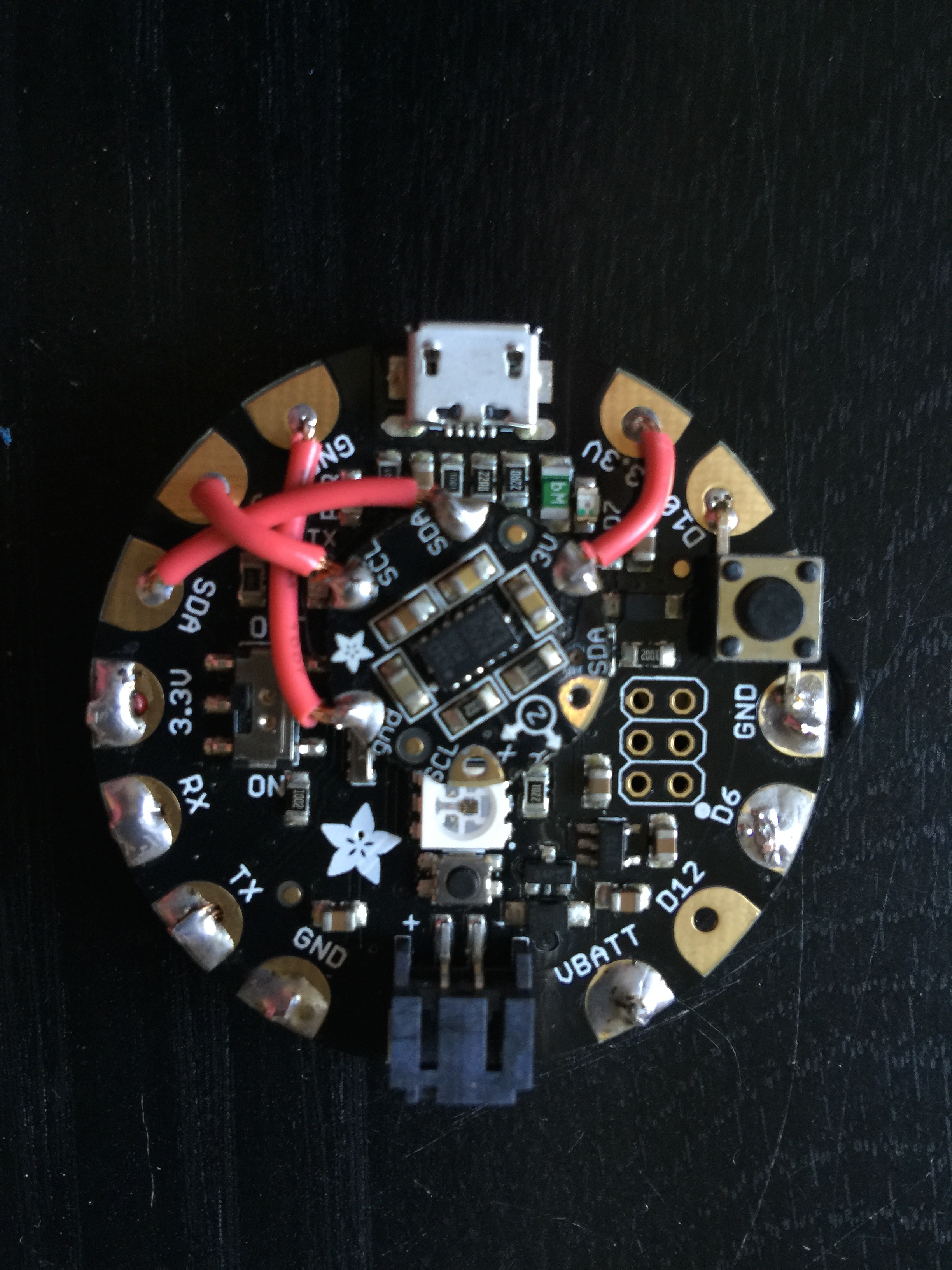
Each module is connected to the FLORA main board individually and stacked to make it look compact and sleek. Below are the pin descriptions of it:
GPS connections:
3.3V to 3.3V
GND to GND
TX to FLORA RX
RX to FLORA TX
NeoPixel connection:
VCC to FLORA VBATT
IN to FLORA D6
GND to GND
Compass connections:
3.3V to 3.3V
GND to GND
SCL to FLORA SCL
SDA to FLORA SDA
Switch:
Between FLORA D10 and GND
After making the connection and soldering all the parts, this is how my final project looks:

