Schematics (Loader) - rain9441/factorio-tls GitHub Wiki
https://github.com/rain9441/factorio-tls/blob/master/screenshots/14-loader-logic-schematics.png Link to Image
The Loader is an independent build separate from the TLS station logic. The purpose of this loader is to provide a smart system that minimizes the buffer waste for your engineering trains. The fundamental principal behind the Loader is to only request items from the logistics network that are going to be on the train. The secondary goal was to allow any configuration of items to be loaded without having to change train cargo wagon filters.
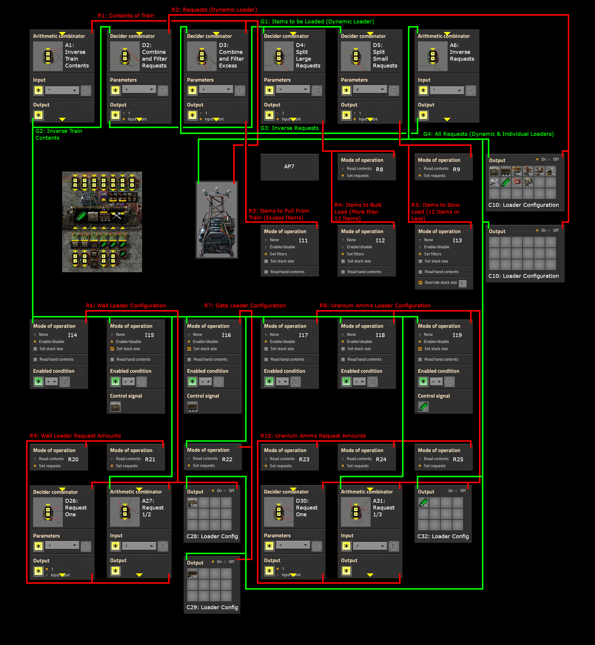
The Loader is split into two parts, the loading logic and the content filtering/progress display. The above image is the schematic for the loader logic. In order to continue, we must assume that red wire (R1) that is connected to the substation in this schematic contains the contents of the train. The green wire (G4) that is connected to the substation will be the channel used to send the aggregate configuration of what we want to load into the train.
The loading logic is broken down further into a dynamic loader and up to six constant loaders. In the above example, we have three different constant loaders, each loading a different item. The purpose of the constant loaders are to provide fast loading for items that are needed in bulk, such as belts or rails. The constant loaders have dedicated stack inserters (one or more) to load the type of item, whereas the dynamic loader has one single stack inserter shared for all item types in the configuration.
The contents of the train (R1) are first sent to an arithmetic combinator (A1) where it is multiplied by -1 to support a subtraction operation. This negative value (G2) is added to the dynamic loader's configuration (R2) and filtered in a decider combinator (D2) to yield only the items that we need to load onto the train (G1), with their respective quantities. The dynamic loader is configured to load whatever is set in the constant combinators (C10). The G1 wire is then connected to two decider combinators (D4, D5) that split the request into two parts. Quantities greater than 12 are taken by D4 and are items we want to load in bulk (R4). Quantities less than 12 are taken by D5 and are items we want to slow load (R5). R4 is connected to a requester chest (R8) that requests the exact amount of items we want to load into the train. R4 is also connected to the stack filter inserter (I12) with a mode of operation of set filters that loads items from the requester chest into the train. This branch of loading will exclusively load any item which we need more than 12 of, so we will never need to worry about over filling the train. The second half of the loader split is the items we want to slow load (R5). This wire is connected to a second requester chest (R9) that requests the exact amount of items we want to load into the train. R5 is also connected to the filter inserter (I13) with a mode of operation of set filters and a stack size of 1. The filter inserter (I13) is responsible for loading the final 12 items of each type that the train needs. Since it has a stack size of exactly 1, it will load one item at a time until the train has enough of that item, and we will not overfill the train.
The last piece of the dynamic loader pulls excess items from the train. For this, we connect the G4 wire, which contains all of the configured items we want on the train (dynamic & individual loaders) to an arithmetic combinator (A6) to invert it so that we can subtract it (G3). The inverse requests (G3) are combined with the contents of the train (R1) into a decider combinator (D3) which filters out only positive values, which is then the items to pull from the train (R3). R3 is connected to a filter stack inserter (I11) witha moder of operation of set filters which pulls items from the train into an active provider chest (AP7) to be recycled by your factory.
The constant loaders are much simpler, and work off of dividing the work among multiple chests. In this example we have three different constant loaders of different sizes. The Wall Loader has two inserters, the Gate Loader has one inserter, and the Uranium Ammo Loader has three inserters. There are blueprints in the core blueprint book for variations of how many inserters an item should have, all you have to do is customize it appropriately.
For the Wall Loader, we configure the amount of walls we want in a constant combinator (C28). It is important to note that we only can have one type of item configured in these loaders. The constant combinator emits its value to R6 as well as G4, which aggregates all requests and sends them to the other half of the TLS Loader system. R6 (Wall Loader Configuration) is is combined with G2 (Inverse Train Contents), which then contains the number of walls we want to load into the train. This value is sent to an Arithmetic combinator (A27) which divides the number in half, sending half the quantity on R9 to each requester chest (R20, R21). In this example, if the train were empty it would send 250 to both requester chests, resulting in a total request of 500 walls. The R6 wire is also sent a decider combinator (D26) which normalizes the configuration to an output count of exactly 1. This value is also outputted to R9, adding exactly 1 wall request to each requester chest. This combinator is in place to ensure that if only one wall is missing, it doesn't get lost due to dividing 1 by 2 (which results in 0). After logistics bots carry the required materials to the requester chests (R20, R21), the stack inserters (I14, I15) will load them into the train. Each stack inserter is connected to both G2 (Inverse Train Contents) as well as R6 (Wall Loader Configuration) and will contain the number of walls we want to load into the train. The first inserter (I15) is configured with an enabled condition of Anything > 0, and is set to set stack size to the wall signal. This inserter can then handle the final set of items into the train in the exact quantity needed. The second stack inserter (I14) is configured to an enabled condition of Anything > 25. This inserter assists in loading until the quantity is low enough that the first combinator can finish the job more precisely. Each subsequent inserter added should have an enabled condition that backs off by 25 units so that the inserters do not accidently overfill the train. This constant loader is a good way to load your trains without having to have a large buffer chest full of materials next to the train at all times. When the train arrives, it will request only the items it needs to fill the train and very little beyond that.
The Gate Loader example is much simpler as it is only a single inserter. For the Gate Loader, we configure it using the constant combinator (C29) and send it again to both R7 as well as G4, which aggregates all requests and sends them to the other half of the TLS Loader system. R7 is combined with G2 to become the amount of gates we want to put onto the train and connected to both the requester chest (R22) as well as the stack inserter (I16). The requester (R22) chest pulls the exact number of items needed. The stack inserter (I16) is configured to an enabled condition of Anything > 0, and is set to set stack size to the gate signal. Like the above, this allows the stack inserter to fill the exact quantity of gates into the train.
The final constant loader, Uranium Ammo, is nearly identical to the Wall Loader, but shows how you can approach dividing the requested items into three inserters instead of two. The only difference is in the arithmetic combinator (A31) that divides by 3 instead of 2. For loading one item with six inserters, you only need to divide by six and connect the wires appropriately.
As the train fills up, there will be times when the requester chests have extra items delivered. This is sometimes due to the fact that items are in the hands of inserters, but not in the chests nor the train. Because of this, you can expect up to about 12-16 items left over of each type in the requester chests near the train. It shouldn't be too impactful for most items, but if you plan on using this for nuclear reactors and you are tight on resources, you may want to haul your reactors manually until you have enough extra resources to carry a small buffer of the expensive nuclear reactors.
The one drawback to this loader so far is that it will be a hot loader. By hot loader, I mean that if there is no train contents present, then the loader will be in a state where it's inserters are fully active and the requester chests are requesting the full quantity of items that it wants to load into the train. This can be problematic if you park a train in manual mode near the inserters as they will fill up a cargo wagon. To remedy this, there is logic in the other schematic which handles the case of no train being present. When no train is docked at the train stop, it simulates a full train by sending the green wire from the substation (G4, all requests for both the dynamic & individual loaders) back on the red wire channel (R1, the contents of the train). That extra logic makes this loader a cold loader, which means it is completely dormant if no train is docked at the train stop in automatic mode.
https://github.com/rain9441/factorio-tls/blob/master/screenshots/13-loader-lights-schematics.png Link to Image
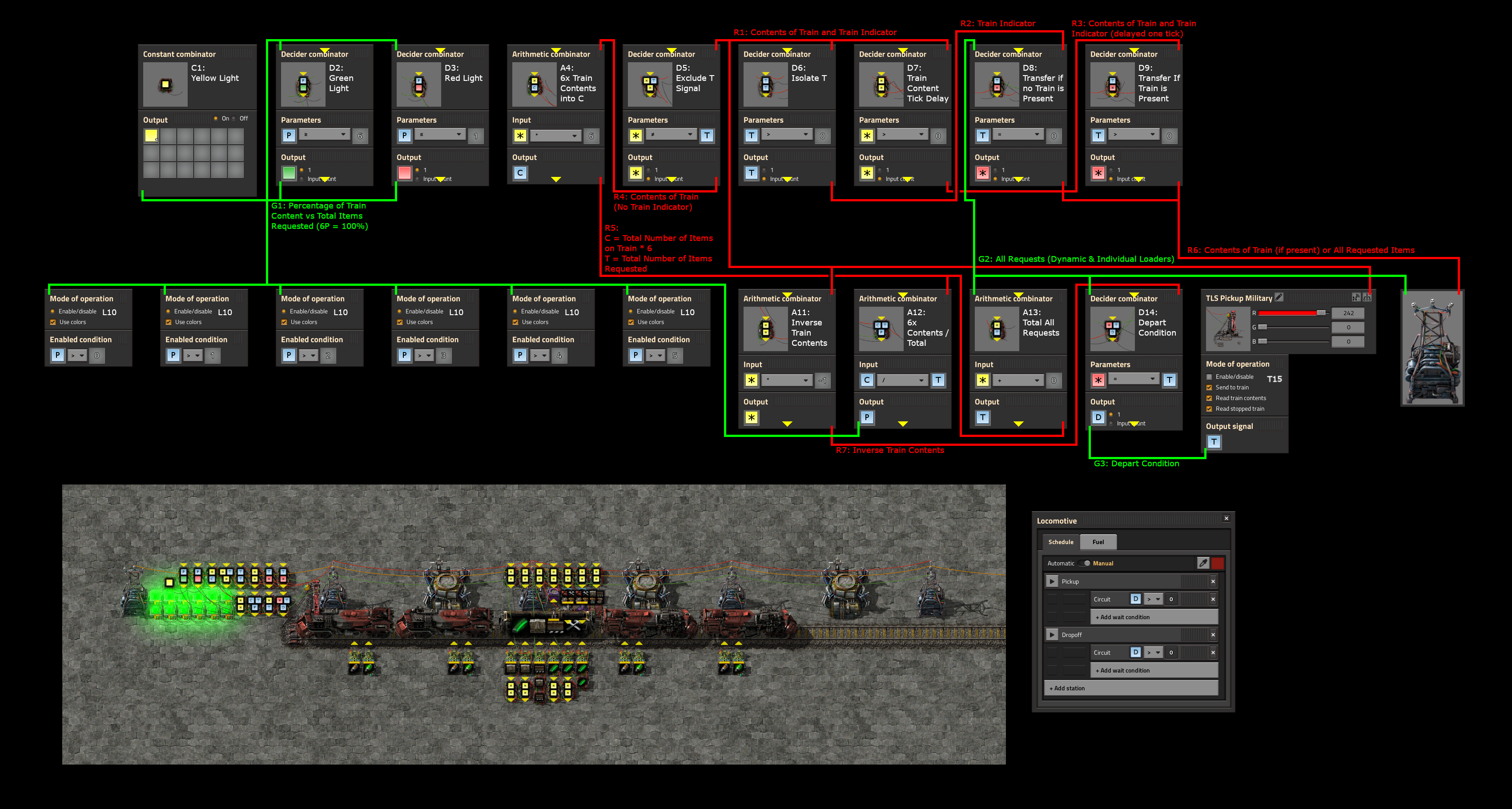
The second part of the Loader is the content filtering/progress display logic. This schematic contains the same assumptions as the loading logic schematic for the wires connected to the substation. The green wire (G2) that is connected to the substation in the schematic contains the configuration of what items should be loaded onto the train. The red wire (R6) that is connected to the substation will be the channel used to send the contents of the train to the loader logic.
The content filtering and progress display logic are obviously two different pieces of this schematic. The content filtering is responsible for taking the contents of the train and determining what to send to the loader logic. This is fairly complex due to the caveat listed above about turning it from a hot loader to a cold loader. The display logic is simpler, and merely gives you a heads up for how full the train is with a fancy colored light display.
To display the train loading progress, we first take the contents of the train from the train stop (T15) and put it on the R1 wire. The train stop is set to read train contents as well as read stopped train into T. This value is sent to a decider combinator (D5) which removes T from the set by outputing Each != T. Since T is some seemingly random non zero number, it should be relatively safe to say that it is not likely the case that any item quantity that the train has equals the train number. Therefore the output of D5 should be all of the contents of the train, but not the train number itself (R4). This value is sent to an arithmetic combinator (A4) where we apply each * 6 into C, this sums up all of the different items and multiplies it by 6 (R5). The requests from the loader logic (G2) are sent to a similar arithmetic combinator (A13) where it applies each + 0 into T to sum up all of the requests (R5). R5 is then processed by an arithmetic combinator (A12) that applies C / T into P, which should give us a value from 0 to 6 representing the percentage of items that the train has loaded (G1) in units of 16.66%. The P signal (G1) is connected to six lights (L10) which are enabled based on P > 0, P > 1, ..., P > 5 to show the progress. Additionally, the P signal (G1) is also connected to a constant combinator (C1) to color the lights yellow. The P signal (G1) connects to decider combinator (D2) to show a green light if P = 6 as well as decider combinator (D3) to show a red light if P <= 1. All of the lights (L10) are configured to use colors, so they will turn red if the train is nearly empty, yellow if it is filling up, and green if it is full. Yellow lights have the lowest priority, so if both a yellow light and a green light are present on G1, the lights will be green. Similarly, if red and yellow were on G1, red would have priority. The priority is based on their location in the signal selection dialog, with colors on the left having the highest priority.
The content filtering is a complex set of combinators that deal with a scenario that is not easily described. The caveat described above about being a hot loader is difficult to solve because of timing issues. Because of the fact that combinators require 1 tick of game time to process, their output is always delayed by one tick. Because of that, if one path of logic goes through two combinators while a second path of logic goes through only one combinator, then there will be a 1 tick difference between when those signals are consumed. This can result in very silly issues, such as inserters swinging exactly once for no reason, or trains departing the moment they arrive. If, for example, you have a train set to depart when D > 0, and the default state of your logic has D = 1, then you may have a timing issue. The train arrives, your logic requires two ticks to run to determine that D should be 0, but the train has already departed because it was already D = 1 the moment the train arrived. For this reason, we are carefully making sure that each logical path for how we are interpreting a train's presence, its contents, and whether it should depart, are all equal in how long it takes for the logic to run. On top of that, we must have a cold depart signal, meaning that if our train departs when D > 0, then the default state of the train stop must be that D = 0.
The train's contents and train number (R1) are read from the train stop (T15) and sent to two decider combinators (D6, D7) to begin branching our logic. On tick 1, the first decider combinator (D6) isolates the T signal and sends it to R2. On tick 1, the second decider combinator (D7) copies the contents of the train and the T signal (R1) into R3. The sole purpose of D7 is to delay the logic by 1 tick. On tick 2, the R2 signal (Train Number) is combined with G2 (All items that should be on the train) and sent to a decider combinator (D8) that ouputs everything if T = 0 into R6. This sends the requests (G2) back to the loader logic (R6), as if the train was full. This ensures that if no train is present, the loader becomes cold (No inserters load anything, no chests request anything). On tick 2, the R3 signal (Contents of train and train number, delayed by one tick) is sent to a decider combinator (D9) which outputs everything if T > 0 into R6. This sends the contents of the train (R1) to the loader logic (R6) to indicate what needs to be loaded. This ensures that if a train is present, the loader becomes hot (Inserters and requester chests are active). On the 3rd tick, our filtered train contents are output in both paths of logic. When a train departs, whatever was the final state of the train's contents will be sent to the loader logic for ticks 1 and 2. On the 3rd tick, the G2 (All requests) will be sent back to the loader logic to simulate a full train. If path of logic that sent the G2 wire to the R6 wire was delayed by one tick, then there would be one tick where the R6 wire (Contents of the train) would be nothing. On that tick, all requester chests would request the full contents of the train, and all inserters would swing in an attempt to load the train that is empty.
To determine when the train should depart, we can send a D = 1 signal to the train stop if the contents of the train match that of the requests. The actual contents of the train (R1) is processed by an arithmetic combinator (A11) which inverses the value so it can be subtracted (R7). R7 (inverse train contents) and G2 (all requests) are combined and sent to a decider combinator (D14) setup to output D = 1 if everything = T into G3. At first this may not seem logical, but the contents of the train also include the train number, so if we take the requests, subtract the train contents, and are only left with T, we know that all of the contents must have equaled the requests. In the unlikely event that your train number is 100, or 200, or 300, you may have a train that departs early on very rare occasions. This is an acceptable risk and can be fixed by adding and removing a wagon to the train to change its number. The G3 wire is connected back to the train stop to send to train to let the train know it can depart.
The loader and unloader are both designed to tell the train when to depart, so your TLS trains can easily be configured with circuit conditions of D > 0 for both the pickup and the dropoff.