Schematics (Dispatcher) - rain9441/factorio-tls GitHub Wiki
https://github.com/rain9441/factorio-tls/blob/master/screenshots/11-dispatcher-schematics.png Link to Image
The second part of the TLS station is the Dispatcher system. The Unloader is designed to allow for any number of different trains to deliver exactly one cargo wagon worth of materials to any Unloader on the map. To do this, each outpost contains a station with the same name that corresponds to a single delivery train. Each outpost can have any number of train stops and receive any number of train deliveries. Each train stop is enabled whenever the outpost needs more resources from it's respective delivery train. As soon as one of the specific train stops are enabled (eg TLS Dropoff Seed), then the corresponding train immediately departs to it. If no stations are enabled, the delivery train stays in the loading bay. The train stop uses an RS Latch to hold it's enabled status. Once it is enabled, it does not disable until a train arrives to unload. This is important because if the train station disabled itself (due to somehow getting enough resources so that it didn't need any more), the train stop would disable causing the delivery train to stop immediately where its at and no path. In effect, the train stops being enabled is how the station dispatches a delivery train to its outpost.
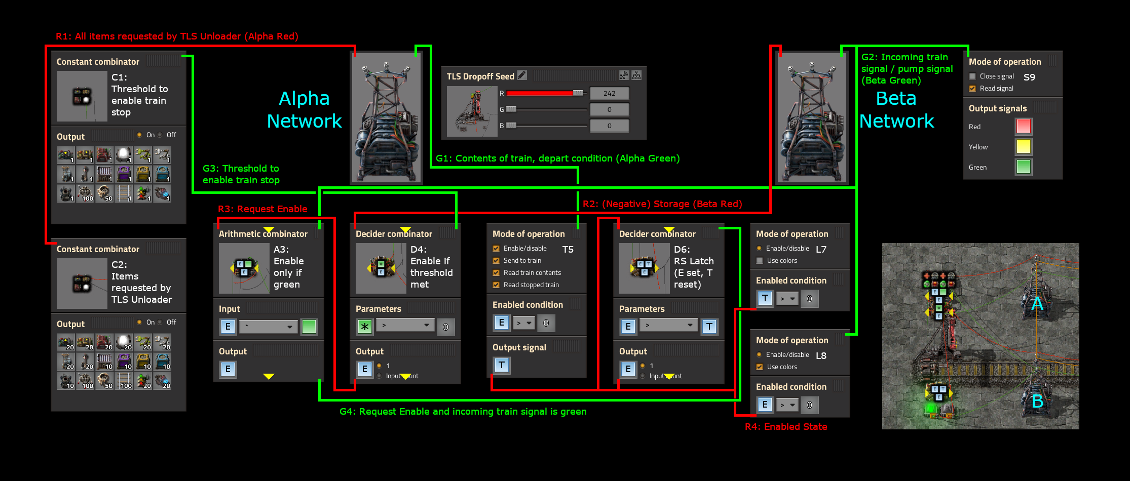
This schematic is for a single train stop. The exact same build can be repeated any number of times for any number of unique delivery trains so long as the combinators are connected to the Alpha and Beta networks appropriately.
The R1 wire is a constant combinator that indicates how many of each item the TLS should pull off of whatever train is unloading. This gets combined with all other train stops' requests in the Unloader logic. The G1 wire is also pulled from the Alpha Network and contains the contents of the train as well as the depart condition (D=1 if the train should depart). The G1 wire connects directly into the train stop. Because we know that there will only ever be one train unloading in any TLS Unloader, we can connect the same green wire to every train stop.
The R2 wire is pulled off the Beta network and contains the negative amount of items in storage, calculated from the unloader logic. The R2 wire is combined with the threshold to enable the train stop (C1 into G3) into D4. The decider combinator determines if there is any positive value (Which is any item that is less than the desired threshold count to summon the build train), and outputs E=1 into R3 to indicate a request to enable the train stop. The R3 wire is merged with the G2 wire off of the Beta Network which contains the incoming train signal (or in the case of fluids, the pump indicator). There is a rail signal that emits it's status to the Green Beta wire. The arithmetic combinator, A3, multiples the E value (request to enable train stop) with the value of green. This effectively outputs an E=1 signal if and only if the incoming train signal is green. The purpose of this logic is to only allow the TLS Unloader to enable a train stop when there is no train currently in the Unloader. This solves an issue where train stops would immediately re-enable themselves when their current train departed because the final items that have been taken off the train are still in the hands of the stack filter inserters. By only allowing a train stop to become enabled when the train unloading bay is clear, we give the system a few seconds to jumble items around before checking to see if our threshold is met for requesting the train. You can also substitute pumps instead of green to only enable the train stop if the pump has been built.
The G4 signal is connected to an RS latch, D6. In this case the set signal is E and the reset signal is T. If E is 1, it will maintain the E=1 signal indefinitely. If the T signal is ever non zero, then the D6 latch will lose its memory state. The R4 wire connects the RS latch (D6) with itself as well as the train stop (T5). The train stop is setup to read stopped train, so it will reset the RS latch when a train arrives.
Finally, the R4 wire is connected to two lights. One light (L7) indicates that a train is present. The other light indicates that the station is enabled (L8). The colors of the network come from G2, which contains the incoming train signal. This gives a fairly obvious warning that a train is coming should you be standing on the tracks. It also helps understand which trains are delivering as well as which train is currently unloading.