PhotonVision - quasics/quasics-frc-sw-2015 GitHub Wiki
We use the BeeLink mini PC for vision processing at this moment; references to a raspberry pi are outdated/from previous seasons. To be cleaned up more
The basic installation process for the a "stock" image running on a Raspberry Pi can be found on the PhotonVision web site.
The PhotonVision team provides an image that is configured to boot as a "read/writable" image. This is great for initial set-up/configuration of the pipeline, but it risks corrupting the filesystem if power is unexpectedly cut to the Raspberry Pi. In our case, this means whenever the robot gets turned off (so... a lot of risk over time).
The solution is to update the OS configuration (preferably after the camera/pipeline is fully in place) so that it will default to booting in a way that the filesystem is treated as read-only data.
There are directions for doing this here, along with information on how to temporarily make the image "writeable" if changes are required (e.g., new versions of the PhotonVision software, updating the camera configuration, etc.).
Step 1: Download current version of photon vision from here - select the most recent revision -> assets -> "photonvision-vXXXX.XX.X-linuxarm64_RaspberryPi.img.xz
Step 2: With the SD card in the computer, use something like Balena Etcher to flash the SD card from the raspberry Pi with the current image.
Step 3: Put the MicroSD card back into the raspberry pi, then configure the pipelines using the web interface. (This should be available here when you're on the same network as the RasPi, so make sure you're connected to the robot and the raspberry pi is also connected before opening this link.) This will let you get the camera set up, resolution, apriltag family, etc. This can be changed later, if needed, but it's easier to do before putting the Pi into read-only mode by default.
Step 4: Disconnect the raspberry pi from the robot's networ, and connect it to a monitor with a mouse, keyboard, ethernet, HDMI, and power.
Step 5: Follow the website guide to configure it for read-only mode, as well as the optional "ro/rw" switcher thing.
- Note, use 'sudo nano [insert file name here]' to open and edit a file. Make the changes, then hit ctrl+o, enter, then ctrl+x to save then exit.
- To log onto the Pi, use the username "pi" and the password "raspberry".
Step 6: Once everything is working, MAKE A CLONE AND SAVE IT. This is a tedious process, so saving yourself the pain of redoing all that makes reimaging it much easier.(You will need another img file to clone the current file, you can download a new raspberry pi image from the GitHub and then overwrite it in said cloning software)
Step 7: If you needed to adjust the pipeline after setting up read-only mode, connect to the raspberry pi through the robot, then log onto it using PuTTY to set the pi to read-write mode before making your changes then returning it to read-only mode. If the changes are major, consider cloning the sd card again just to be safe.
Notes:
- The process of configuring the Pi to boot in read-only mode is somewhat complex (lots of steps). You'll need to have the Pi plugged into a network with Internet access, and it's easiest if you can have both a keyboard/monitor connected to it (for console access) and can connect to it via SSH (e.g., using "Putty" to connect to "photonvision.local" as user "pi", password "raspberry"). The easiest way to do this is to go to one of the monitors, unplug the mouse, keyboard, hdmi, and ethernet cable and plug them all into the raspberry pi. Then plug the power in (micro usb or usb c)
- Because this process is complex, it's a very good idea to make a backup image of the RasPi's SD card before you get started (so, capturing any initial PhotonVision pipelines, etc.), and after you've got everything working (so that you can quickly deploy a replacement image if things happen like your RasPi's SD card getting physically damaged; "ask us how we know!").
- When asked to edit a file, using "sudo nano [insert file locations]" and make the required edits
- Corrections to the tutorial (Check here if anything is spitting back errors):
- When creating the read-only and read-write swap command, remove the " ; sudo mount -o remount,ro /boot" part from the parts that say alias and replace it with " ; sudo systemctl daemon-reload"
- When making the bash.bash_logout file, make sure to add "sudo" before the commands, additionally, omit the "mount -o remount,ro /boot" and add the command "sudo systemctl daemon-reload"
- Once the Bee Link is configured (TODO: How was this done?), connect it to the roboRio. Connect to http://photonvision.local:5800/#/dashboard. Note that if you put in
https://, you will likely get a security warning. This is because the photon vision setup does not provide secure HTTP, so the browser tries to protect you from treating it like a secure website. (By puttinghttp://we are telling the browser that we do not expect the website to be secure/encrypted). - Go to the "Camera Matching" tab to activate the connected cameras.
- Go to the "Settings" tab to import old settings (These are checked into Git for 2025 here.), or export current settings (Please check them into git!)
- If it is not connecting to the smart dashboard, check that your "Team Number/Network Tables address" is set to 2656.

-
How to backup/restore a RasPi SD card
- This is helpful to be able to "snapshot" versions of the RasPi installation as you make progress. (For example, after initial setup of PhotonVision with an initial pipeline, or after configuring the Pi to automatically boot as read-only, etc.)
Linking April Tags with Autonomous Code: Here are the calculations under the 2023 charged up code, DriveWithVision, that at least try to explain how it was found where the robot should end up being.


It was helpful to also install the following software packages (using sudo apt-get install <PACKAGE_NAME>):
- net-tools
- avahi-utils
- avahi-daemon
- overlayroot
It was also helpful to set up configurations for the avahi-daemom, which lets you "discover" the computer via Zero-conf/Bonjour, advertising the following services (and using "%h" for service names):
As discussed in the set-up docs referenced above, installing PhotonVision will also add the "network manager" service to the machine, which will significantly slow down the boot process. The docs talk about how to disable this service, and this is also discussed in a number of places on the net, including this post on "AskUbuntu".
The docs above talk about how to use "overlayroot" to boot the box in read-only mode in order to keep the SSD from being corrupted in case of an "unexpected power failure", which is very important for us since power can fail at any time. (Specifically, when the robot is turned off.) However, the "how-to" is a little sketchy.
What Mr. Healy has done on our box for 2024 is outlined below. (Note: at each step along the way, the changes were tested by re-running sudo update-grub and then rebooting the box and performing the specified confirmation steps.)
- Update
/etc/default/grubwith the following settings:
# timeout styles: hidden (default on install), menu, countdown
GRUB_TIMEOUT_STYLE=menu
# timeout in seconds (default on install was 0)
GRUB_TIMEOUT=3
- Confirmation steps: on reboot, the computer should display a menu of boot configurations and let you select which one to use; after 3 seconds, it should simply boot using the first configuration.
- Set up an additional option in GRUB2, allowing us to configure an alternate boot mode, using the approach discussed here.
Changes to/etc/default/grub:
export GRUB_CMDLINE_LINUX_EXTRA=""
Changes to /etc/grub.d/10_linux:
# mhealy: Start of second (custom) option
linux_entry "${OS} (test)" "${version}" simple \
"${GRUB_CMDLINE_LINUX} ${GRUB_CMDLINE_LINUX_DEFAULT} ${GRUB_CMDLINE_LINUX_EXTRA}"
# mhealy: End of second (custom) option
- Confirmation steps: on reboot, the computer should include a new boot configuration ("Ubuntu (test)") in the menu. Selecting this option should boot normally.
- Change the
GRUB_CMDLINE_LINUX_EXTRAvariable in/etc/default/grubto be:export GRUB_CMDLINE_LINUX_EXTRA="quiet splash"
- Confirmation steps: on reboot, boot using the configuration you've added. The boot should run normally, but nearly all of the messages displayed during the boot should be hidden.
- Change the
GRUB_CMDLINE_LINUX_EXTRAvariable in/etc/default/grubto be:export GRUB_CMDLINE_LINUX_EXTRA="overlayroot=\"tmpfs:swap=1,recurse=0\""
- Confirmation steps: on reboot, boot using the configuration you've added. Log on, and create a test file (can be empty) in your home directory. Reboot (again, using the new configuration), log on, and confirm that the test file isn't there.
- Make some final changes to the configuration files:
Change theGRUB_DEFAULTvariable in/etc/default/grubto be:
GRUB_DEFAULT=1 # Default to the read-only configuration (#2 in the list)
Change the line in /etc/grub.d/10_linux that generates the new configuration to:
# mhealy: Start of second (custom) option
linux_entry "${OS} (read-only)" "${version}" simple \
"${GRUB_CMDLINE_LINUX} ${GRUB_CMDLINE_LINUX_DEFAULT} ${GRUB_CMDLINE_LINUX_EXTRA}"
# mhealy: End of second (custom) option
- Confirmation steps: on reboot, the new configuration should now be named "Ubuntu (read-only)", and should be selected by default.
Notes:
- We tried following some guidance on the GRUB2 settings, and making additional changes to
/etc/default/grubthat would allow us to remember the selected boot configuration, making it a little easier to flip back and forth during testing, etc. However (as might be expected), booting in read-only mode meant that the last boot mode wasn't saved. - Some other settings can be configured in GRUB2, as outlined here.
- Per Beelink's technical support, the barrel jack size for the power interface is 5.5mm x 2.5mm.
- Configuring a Beelink EQ* for autoboot on power-on
- If someone accidentally installs/enables a graphical login, this can significantly impact the machine's performance. Be sure to switch it back to a "multi-user" default (resource 1, resource 2)
- Install the OrangePi PhotonVision image on an SD card, and boot the OrangePi.
- Default account is user
pi, passwordraspberry. - Note that the directions provided by PhotonVision indicate that additional steps are needed on an OrangePi 4 that aren't required for an OrangePi 5.
- Change default shell to Bash via
chsh, and type/usr/bin/bashwhen prompted for the new shell.
- This will change the default command interface to something that supports arrow keys for history/editing, along with other "niceties".
- After changing the shell, you may want to log out and back in again (allowing it to take effect)
- Update the system:
sudo apt-get updatesudo apt-get upgradesudo apt-get dist-upgradesudo reboot
- Install additional packages:
sudo apt-get install net-tools avahi-utils avahi-daemon overlayroot - Set up advertising configurations for the avahi-daemom, which lets you "discover" the computer via Zero-conf/Bonjour, advertising the following services (and using "%h" for service names):
- Default Debian image password:
orangepi - Directions to get a Debian image booting on the OrangePi are on the OrangePi wiki.
Base directions are available on the PhotonVision site
Based on Mr. Healy's experiments with the process outlined above, there appear to be some additional "tweaks" that are needed on the Romi.
-
The Romi currently needs to be in "read/write" mode whenever PhotonVision is running (including when auto-started).
- The PhotonVision docs suggest that this is only needed when trying to save logs and configurations; however, the program appears to fail to load the configuration or connect to the camera if the Romi is in read-only mode when you connect to the PhotonVision server via a web browser.
- A bug has been filed about this with the PhotonVision team.
- For now, a work-around appears to be to connect to the Romi web interface first, and switch the Romi to "writeable" before connecting to the PhotoVision web interface.
-
The memory being allocated for the JVM when running PhotonVision appears to be too low.
- The file at
/lib/systemd/system/photonvision.serviceshould be updated to change the-Xmx512mparameter (.5GB) to-Xmx1024m(1GB). (If you're not familiar with editing files under Linux, please talk to Mr. Healy.)
- The file at
-
The installer provided for "Other Debian-Based Co-Processor Installation" appears to install the generic JAR file (for use on Windows, Linux, etc.).
- This is documented in an existing bug with the PhotoVision project.
- There is a separate JAR file in the PhotonVision download set that is apparently specific to the Raspberry Pi; this file needs to be downloaded to the Pi, moved into the correct directory, and reconfigured for appropriate use.
- For example:
% sudo wget "https://github.com/PhotonVision/photonvision/releases/download/v2023.1.1-beta-6/photonvision-v2023.1.1-beta-6-raspi.jar" -O /opt/photonvision/photonvision.jar
% sudo chown root.root /opt/photonvision/photonvision.jar
% sudo chmod a+x /opt/photonvision/photonvision.jar
-
For Gladys:
- PhotonVision app
- SSH as [email protected]
- The hostname "photonvision.local" may work, but it depends on mDNS resolution being enabled
-
Sally Raspberry Pi SSH login
- Username: pi
- Password: raspberry
-
For Romi:
- Using PhotonVision in FRC (presentation from Dec2023 SCRA Academy)
This should simply be a matter of:
- Bringing up Shuffleboard on the driver's station
- Pulling open the tab on the left-hand side of the window
- Clicking on the "Camera Server" section
- Dragging one of the camera streams onto a sufficiently large region of the main window
Worst-case scenario, you can also try opening a web browser and pointing it at either the raw image stream or the processed stream, and then adjusting windows on the laptop to suit the drive team's needs.
- If the Camera Server list is empty:
- Make sure that the coprocessor running PhotonVision is actually running.
- Make sure that PhotonVision is running on the coprocessor (e.g., try connecting to http://photonvision.local:5800, assuming that the coprocessor's hostname is "photonvision").
- Make sure that the camera(s) are detected, and the image streams are active (e.g., by checking the main page for PhotonVision on the coprocessor, or browsing the streams directly).
- Check the configuration settings in PhotonVision, and make sure that the team number is configured. (If it isn't, then PhotonVision won't "know" what robot to connect to in order to publish the information.)
Raspberry pi installation instructions
Download the raspberry pi image from the photonvision releases. Use BalenaEtcher to flash the image onto a MicroSD card, and then insert the MicroSD into a raspberry pi. Provide power and wait for installation.
Connect the raspberry pi to the RoboRio for power (usb into RoboRio, usb-c into pi). Connect the pi to the camera over ethernet.
Go to photonvision.local:5800 when connected to the robot for the photon vision dashboard. Make sure the correct april tag family is selected to be able to track april tags.
PLEASE NOTE. In order for the Estimation to Work Successfully, Photonvision must be extensively calibrated to its designated setting. Please see this (https://docs.photonvision.org/en/latest/docs/getting-started/pipeline-tuning/calibration.html)
Photon Vision pose estimator documentation
Create a camera with
photonlib::PhotonCamera camera{"USB_Camera"};
Create an AprilTagFieldLayout. For a game, WPILib provides a file with the april tag layouts for the game. For other testing, an AprilTagFieldLayout can be created with a vector of AprilTag objects like in the example below (example measurements are used).
  std::vector<frc::AprilTag> tags = {
      {586, frc::Pose3d(0_in, 0_in, 17_in, frc::Rotation3d())},
      {0, frc::Pose3d(60_in, 265.0_in, 20.5_in,
                      frc::Rotation3d(0_deg, 0_deg, -90_deg))},
      {1, frc::Pose3d(26.5_in, 253.0_in, 20.5_in,
                      frc::Rotation3d(0_deg, 0_deg, -90_deg))},
      {585, frc::Pose3d(126_in, -62_in, 17_in,
                        frc::Rotation3d(0_deg, 0_deg, 180_deg))}};

  frc::AprilTagFieldLayout aprilTags =
      frc::AprilTagFieldLayout(tags, 54_ft, 27_ft); // FRC field size is 54 by 27 feet
Measure the distance from the camera to the center of the robot. If the camera is on the front of the robot and facing forward, the positive X direction should be used for the Transform3d with 0 rotation.
  frc::Transform3d robotToCam =
      frc::Transform3d(frc::Translation3d(0.3048_m, 0_m, 0.0_m),
                       frc::Rotation3d(0_rad, 0_rad, 0_rad));
Finally, create a PhotonPoseEstimator. Other options besides CLOSEST_TO_REFERENCE_POSE are in the photonvision documentation.
  photonlib::PhotonPoseEstimator estimator = photonlib::PhotonPoseEstimator(
      aprilTags, photonlib::CLOSEST_TO_REFERENCE_POSE,
photonlib::PhotonCamera("USB_Camera"), robotToCam);Read the WPILib pose estimator documentation. It combines vision measurements from PhotonPoseEstimator with measurements from the encoders and gyro to get the robot's position even when it can't see an AprilTag. Example code below
  frc::DifferentialDriveKinematics m_kinematics{
    units::meter_t{RobotPhysics::TRACK_WIDTH_INCHES_GLADYS}};

  frc::DifferentialDrivePoseEstimator m_poseEstimator{
    m_kinematics, m_gyro.GetRotation2d(), GetLeftDistance(),
    GetRightDistance(), frc::Pose2d{}};

  PhotonLibVision m_PhotonVision;
The DifferentialDrivePoseEstimator should be updated with regular odometry measurements
  m_poseEstimator.Update(m_gyro.GetRotation2d(), GetLeftDistance(),
                         GetRightDistance());
The previous calculated positions should also be regularly stored in m_poseEstimator. Do this in the periodic function
auto result = m_PhotonVision.UpdateFieldPosition(
      m_poseEstimator.GetEstimatedPosition());
  if (result) {
    m_poseEstimator.AddVisionMeasurement(
        result.value().estimatedPose.ToPose2d(), result.value().timestamp);
This code puts basic debug output on the SmartDashboard
  frc::Pose2d robotPose = GetEstimatedPose();
  frc::SmartDashboard::PutNumber("X position", robotPose.X().value());
  frc::SmartDashboard::PutNumber("Y position", robotPose.Y().value());
frc::SmartDashboard::PutNumber("Yaw", robotPose.Rotation().Degrees().value());The camera will use its known position and angle and from the orientation of the april tag determine the robots position, from there the robot has the ability to face the tags geometric center and drive to it. For this please look here (https://docs.photonvision.org/en/latest/docs/examples/index.html)
Here is the example code below this will be in the PhotonVision.cpp file
bool PhotonLibVision::AprilTagTargetIdentified(int IDWantedTarget) {
  photonlib::PhotonPipelineResult result = camera.GetLatestResult();
  if (result.HasTargets()) {
    std::span<const photonlib::PhotonTrackedTarget> targets =
        result.GetTargets();
    for (const photonlib::PhotonTrackedTarget& target : targets) {
      int targetID = target.GetFiducialId();
      if (targetID == IDWantedTarget) {
        // std::cout << "ID " << IDWantedTarget << "Acquired" << std::endl;
        return true;
      }
    }
  }
  return false;
}

std::optional<photonlib::PhotonTrackedTarget>
PhotonLibVision::GetIdentifiedAprilTarget(int IDWantedTarget) {
  photonlib::PhotonPipelineResult result = camera.GetLatestResult();
  if (result.HasTargets()) {
    for (const photonlib::PhotonTrackedTarget& target : result.GetTargets()) {
      int targetID = target.GetFiducialId();
      if (targetID == IDWantedTarget) {
        return target;
      }
    }
  }
  return std::nullopt;
}


bool PhotonLibVision::CalculateDistanceAndAnglesToTarget(
    int idWantedTarget, units::meter_t& distance, units::degree_t& pitchTarget,
    units::degree_t& yawTarget) {
  auto possibleTarget = GetIdentifiedAprilTarget(idWantedTarget);
  if (!possibleTarget.has_value()) {
    return false;
  }

  auto target = possibleTarget.value();

  const units::degree_t pitchToTarget(target.GetPitch());
  const units::degree_t yawToTarget(target.GetYaw());
  units::meter_t range = photonlib::PhotonUtils::CalculateDistanceToTarget(
      PhotonVisionConstants::CameraAndTargetValues::CAMERA_HEIGHT,
      PhotonVisionConstants::CameraAndTargetValues::TARGET_HEIGHT,
      PhotonVisionConstants::CameraAndTargetValues::CAMERA_PITCH,
      pitchToTarget);

  distance = range;
  pitchTarget = pitchToTarget;
  yawTarget = yawToTarget;
  return true;
}
The constants will be measured values. For refrences visit the constants.h file
An example command for utilizing these functions to drive to the april tag can be found in the 2023 Charged Up Project under the AprilTagDriveToTarget.cpp
The main portion of the code that goes into the initialize and execute is here:
void AprilTagDriveToTarget::UpdateDrivingParameters() {
  bool targetFound =
      m_photonLibVision->AprilTagTargetIdentified(m_targetToDriveTo);
  if (targetFound == true) {
    m_photonLibVision->CalculateDistanceAndAnglesToTarget(
        m_targetToDriveTo, m_distance, m_pitchTarget, m_yawTarget);
    double forwardSpeed = -forwardController.Calculate(
        std::abs(m_distance.value()),
        PhotonVisionConstants::CameraAndTargetValues::GOAL_RANGE_METERS
            .value());
    // adding extra speed

    if (forwardSpeed > 0) {
      forwardSpeed = forwardSpeed + 0.2;
    } else {
      forwardSpeed = forwardSpeed - 0.2;
    }
    // deleted a negative sign in rotationSpeed
    double rotationSpeed = turnController.Calculate(m_yawTarget.value(), 0);

    m_drivebase->ArcadeDrive(forwardSpeed, rotationSpeed);
    m_drivebase->SetBrakingMode(true);
  }
}
Essentially it is utililzing the functions in the Photonvision.cpp file and then adding buffer zones to make sure the robot can overcome static friction. The "forwardController" and the "turnController" are basic PID controller Setups that can be found in the .h file. and their values were manually tuned and can be found in the constants.h file
The is finished will simply be a check for if the robot is within its boundaries of error:
bool AprilTagDriveToTarget::IsFinished() {
  if (std::abs(m_distance.value()) <
          (PhotonVisionConstants::CameraAndTargetValues::GOAL_RANGE_METERS
               .value()) &&
      ((m_yawTarget > -2_deg) && (m_yawTarget < 2_deg))) {
    return true;
  }
  return false;
}Brief Note: Refrence the "Drivebase Test + PhotonVision" under the experimental 2023 directory. Then access the TrajectoryGenerator.cpp file.
The first constructor is the default code for building trajectories via pathweaver. Almost a one for one copy/paste from WPILIB (found here https://docs.wpilib.org/en/stable/docs/software/pathplanning/trajectory-tutorial/index.html and here https://docs.wpilib.org/en/stable/docs/software/pathplanning/pathweaver/integrating-robot-program.html). This does not use vision currently.
The 2nd Constructor can create any trajectory, but is used in our case in tandem with April Tag Code to be able to drive straight lines based on the input given from april tags. The code that utilizes it can be found in the same project "Drivebase Test + PhotonVision" under the RobotContainer.cpp. Here is the code below:
frc::Pose2d startingPose = m_drivebase.GetEstimatedPose();
  units::degree_t startingAngle = startingPose.Rotation().Degrees();

  units::meter_t endingXPosition = startingPose.X() + distance * startingPose.Rotation().Cos();
  units::meter_t endingYPosition = startingPose.Y() + distance * startingPose.Rotation().Sin();

  frc::TrajectoryConfig config{0.2_mps, 0.4_mps_sq};
  bool driveForward = true;
  if (distance < 0_m) {
    driveForward = false;
  }
return BuildTrajectoryUsingAprilTags(startingPose, frc::Pose2d(endingXPosition, endingYPosition, startingAngle), driveForward, &m_drivebase);
The 3rd Constructor creates a manual trajectory (a.k.a. not using pathweaver) by the user providing the startpoints, endpoints, midpoints etc. Remember that the 3rd constructor does not use vision, so whatever direction the robot is facing will become the positive x direction.
Using cv-inrange-demo.py on the example image captured, the following bounding values were obtained for the retro-reflective tape on the high goal:
- H: 21/77
- S: 31/255
- V: 148/255
- A computer with SD card reader/writer
- A micro SD card (with SD adapter, if needed for reader)
- Network connection
- Raspberry Pi
-
The instructions outlined under "Process" (below) assume that you're using a Microsoft Windows computer.
- The same tasks can be done using a Mac/Linux/ChromeOS box, but some pieces (e.g., the software used to burn the image to an SD card, or to clone it for backup after configuration) will be different.
- See the Raspberry Pi website for some additional information.
-
Always try to use a second SD card when installing a new Raspberry Pi image.
- This allows you to keep the SD card already in use for vision on the robot as a fully-configured fallback, just in case anything goes wrong during setup.
- It's also a good idea to keep the card configured with the old software as a backup for at least a little while (e.g., until after the new image has been fully tested and proven to be working as needed).
- Get SD card with adapter and plug into computer, the opening on the computer should look something like this
- Then go to https://github.com/wpilibsuite/WPILibPi/releases and scroll down until the downloads are shown they will be under the Assets drop down menu(see image) the download you want to click will be something like this: WPILibPi_image-v2021.3.1.zip the numbers will be different due to the latest release available.
- Save the download release into the file explorer where it can be accessed for later.
- Launch the "Etcher" app.
- If this is not installed on the machine, go to https://sourceforge.net/projects/etcher.mirror/, download the installer, then install the application on the machine.
- After launching "Etcher", a grey tab will open and you need to click the button flash from file
- Select the file that you have downloaded earlier and then select the SD card in the menu that appears.
- Once SD card is flashed you have updated it, but its setting have been reset to default (e.g., wrong team number, camera customization and vision processing app are lost, etc.). It is recommended that you plug the SD card back into the Raspberry Pi in order to change its setting to its correct ones.


- Plug the SD card into the Raspberry Pi on the robot, and then turn the robot on.
- Connect to it through the Robot's radio (the same way as you would connect to any wifi network).
- Open a browser and type http://wpilibpi.local/ into the browser search bar.
- It is recommended to stay in the "Read Only" mode for as much as possible. When switching one of the settings first switch into the Write mode, save the changes, and then switch back to "Read only" mode.
- The following settings need to be altered (you will need to toggle tabs on the left hand side of the screen in order to get to the settings):
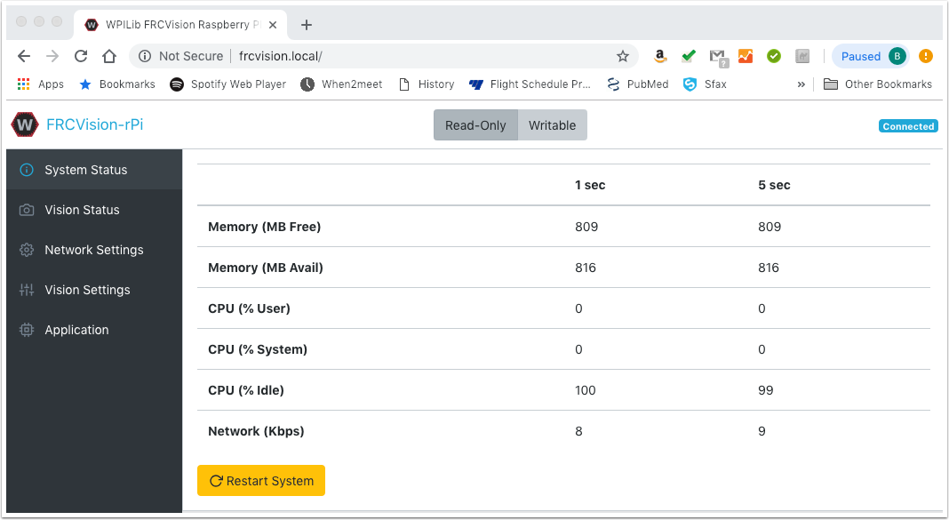
- Change the team number to your current team number (e.g., "2656").
- Change the Camera Resolution to the according resolution and frames (check with coaches).
- If an app should be installed on the RasPi for vision process (e.g., as was done for "Infinite Recharge At Home"), upload it to the RasPi.
- TODO: Add steps for how to confirm the settings added above, especially camera.
- After updating the configuration, create a back up image on your laptop by first removing the SD card from the RasPi, putting it into the adapter, and plugging it back into the computer.
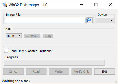
- Open Windows Disk 32 Imager.
- If the computer doesn't have the application, it can be installed from https://sourceforge.net/projects/win32diskimager/.
- If the computer doesn't have the application, it can be installed from https://sourceforge.net/projects/win32diskimager/.
- Create a place for the imaging file to be placed and then read the SD card. Once the SD card is read, there is now an image backup on the computer.
- Note: To re-image other SD cards, you can use the backup image (rather than the "default" version downloaded from GitHub) and follow steps 4 - 6 from the "Burning the new image" section (above), using the backup copy on the computer.
- The settings should not need to be changed when using the backup image, as it is already configured for the team's robot.