viewshed_example - ptabriz/geodesign_with_blender GitHub Wiki

Processing, shading and rendering geospatial data
In this example we will learn how to setup blender GIS addon and georeference the scene. We will also review the procedure for importing, processing and shading vector and raster data. We will proceed with the instructions using a simple viewshed assignment. Assignment goal is to visualize and compare viewshed simulations computed for 4 different locations across a site. The general workflow is as following.
Note: Viewshed is a raster map showing a surface's visible areas from a given location.
There are two ways to complete the example; Scripting method (using blender's Python editor) and GUI (graphical user interface) method. For each step, the GUI procedure is listed as bullet points. Below that you can find the code snippet if you would like to follow the Scripting procedure. To execute the code snippet open a new text file in Text Editor and for each step directly copy-paste the code snippet into the editor and click on Run Script to execute the code.
| Method | Duration | difficulty |
|---|---|---|
| GUI | 1-2 hours | Complex |
| Python editor | 10-15 minutes | Easy |
Note For better learning complete the example with both methods but do not mix and match. Try to follow one method from the beginning to the end.
Contents:
I. Setting up the scene II. Georeferencing the blender Scene III. Importing digital surface model IV. Importing shapefile V. Shading the scene VI. 3D modeling made easy: scripting procedure
Required software and materials
- Download and install latest version of Blender from here.
- Download and install Blender GIS addon from here. Installation guide available here.
- Download and unpack viewshed_tutorial_data.zip from here
I. Setting up the scene
The first step is to clean the scene and setup rendering and lighting parameters.
GUI
- Run Blender and open the file example_viewshed.blend.
- Select the default Cube object in 3D viewport and delete it (right-click on the object ‣ press delete ‣ ok )
- Make sure that the render engine is set to "Cycles". You can find it in the top header, the default is Blender Render
- To increase the Lamp elevation and change the Lamp type to Sun for appropriate lighting:
- Left click on the Lamp object in Outliner to select it
- Go to Properties editor ‣ Object (the orange cube icon) ‣ Transform panel ‣ in the Location matrix, change the Z value to 1000 (see below figure if needed)
- For geospatial models you need a more powerful light source. To change lamp type to Sun and increase the emission:
- In Properties editor ‣ Lamp (two icons to the right of the Object icon) ‣ expand the Lamp panel ‣ Change lamp type to Sun
- Expand the Nodes panel ‣ Click on Use Nodes to enable modifying Sun parameters.
- Set the Strength parameter to 6.00
Python editor
import bpy
# remove the cube
cube = bpy.data.objects["Cube"]
cube.select = True
bpy.ops.object.delete()

# change lamp type and elevation
import bpy
lamp = bpy.data.lamps["Lamp"]
lamp.type = "SUN"
lampObj = bpy.data.objects["Lamp"]
lampObj.location[2] = 1000

# Setup node editor for lamp and increase the lamp power
lamp.use_nodes = True
lamp.node_tree.nodes["Emission"].inputs[1].default_value = 6

# Set render engine to cycles
bpy.context.scene.render.engine = 'CYCLES'
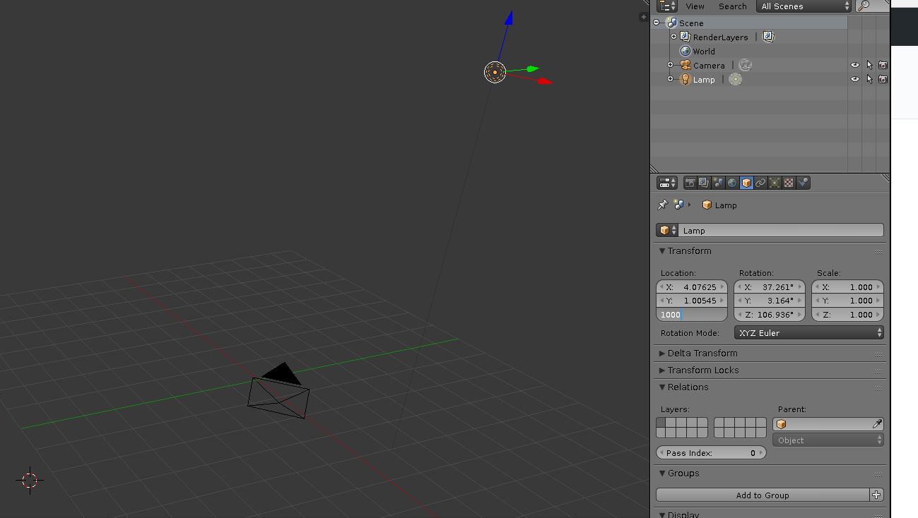 Changing the lamp elevation Changing the lamp elevation |
|---|
II. Georeferencing the Blender Scene
Setting up Blender GIS addon
- Download the BlenderGIS addon
- Go to file ‣ user preferences (
Alt + Ctrl + U) ‣ Add-ons ‣ Install from File (bottom of the window) - Browse and select "BlenderGIS-master.zip" file
- You should be able to see the addon 3Dview: BlenderGIS added to the list. If not, type "gis" in the search bar while making sure that in the Categories panel All is selected. In the search results you should be able to see 3Dview: BlenderGIS. Select to load the addon.
- From the bottom of the preferences window click Save User Settings so the addon is saved and autmatically loaded each time you open blender
Adding a new predefined coordinate reference system (CRS)
Before setting up the coordinate reference system of the Blender scene and configuring the scene projection, you should know the Coordinate Reference System (CRS) and the Spatial Reference Identifier (SRID) of your project. You can get the SRID from http://epsg.io/ or spatial reference website using your CRS. The example datasets in this exercise uses a NAD83(HARN)/North Carolina CRS (SSRID EPSG: 3358)
- In BlenderGIS add-on panel (in preferences windows), select to expand the 3D View: BlenderGIS
- In the preferences panel find Spatial Reference Systems and click on the + Add button
- In the add window put "3358" for definition and "NAD83(HARN)/North Carolina" for Description. Then select Save to addon preferences
- Select OK and close the User Preferences window
 Installing addon and setting up Coordinate System Installing addon and setting up Coordinate System |
|---|
Learn more about Georeferencing management in Blender
Setting up the scene coordinate system
GUI
- Find and click on GIS addon’s interface in 3D viewport’s left toolbar. In the “Geoscene” panel , click on the gear shape icon and switch to NAD83(HARN), click ok.
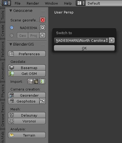 Georeferencing setup in Blender GIS Georeferencing setup in Blender GIS |
|---|
III. Importing digital surface model
Rasters can be imported and used in different ways. You can import them As DEM to use it as a 3D surface or as_Raw DEM_ to be triangulated or skinned inside Blender. You can select On Mesh to drape them as a texture on your 3D meshes. In this example, we import a digital surface model (DSM) derived from Lidar data points dataset as a 3D mesh using As DEM method. Note: Blender GIS imports both Digital Elevation Model (DEM) and Digital Surface Model (DSM) through As DEM method.
GUI
- Go to file ‣ import ‣ Georeferenced Raster
- On the bottom left side of the window find Mode and select As DEM
- Set subdivision to Subsurf and select NAD83(HARN) for georeferencing
- Browse to the 'workshop_material' folder and select 'example1_dsm.tif'
- Click on Import georaster on the top right header
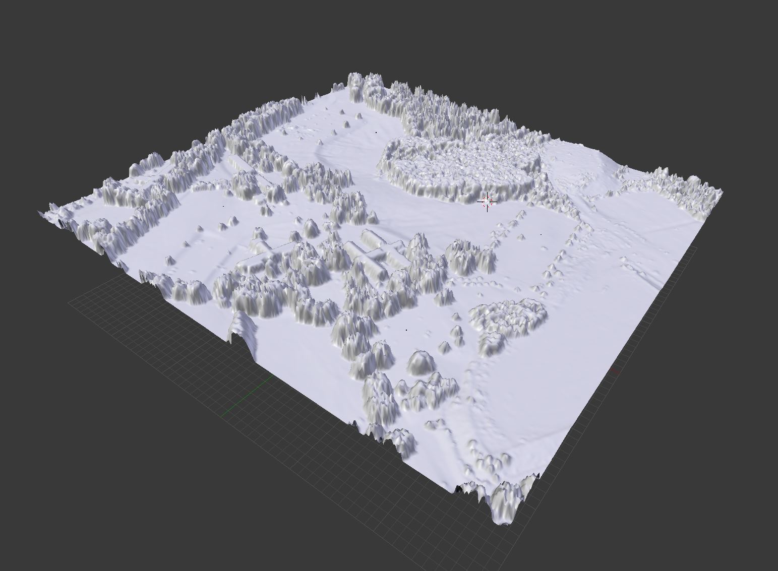
- If all the steps are followed correctly, you should be able to see the terrain in 3D view window
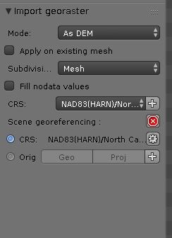 Georaster import parameters Georaster import parameters |
|---|
Python editor
import bpy
import os
filePath = os.path.dirname(bpy.path.abspath("//"))
fileName = os.path.join(filePath,'example1_dsm.tif')
bpy.ops.importgis.georaster(filepath=fileName,
                            importMode="DEM", subdivision="subsurf",
                            rastCRS="EPSG:3358")
Surface subdivision and refinement
Usually when surface or elevation models are imported in Blender they are downsampled to a defaults subdivision resulting in smoothing out the surface details. The following procedure subdivides the imported mesh into smaller faces to enhance the surface representation. In this step we increase the subdivision units to acquire a more detailed surface.
GUI
- Select surface model (right click on the object)
- Go to 3D view editor's bottom toolbar ‣ Object interaction mode ‣ Edit Mode
- Switch to Face select
- If object is not orange in color (i.e., nothing is selected), go to Select ‣ (De)select All (or press
A) to select all faces (when the object faces are selected, they will turn orange) - Go to Tools (left toolbar) ‣ Mesh Tools ‣ Subdivide . The subdivide dialogue should appear on the bottom left on the toolbar. Type "4" in the number of cuts tab
- Go to 3D view editor's bottom toolbar ‣ Object interaction mode ‣ Object Mode . You should be able to see the surface details at this point (bottom figure, right image).
Python editor
import bpy
bpy.ops.object.mode_set(mode='EDIT')
bpy.ops.mesh.select_all(action='SELECT')
bpy.ops.mesh.subdivide(number_cuts=4, smoothness=0.2)
bpy.ops.object.mode_set(mode='OBJECT')
 DSM surface after importing DSM surface after importing |
 DSM surface after subdivision DSM surface after subdivision |
|---|
IV. Importing viewpoint shapefile
In this step we will import viewpoint locations as a point feature shapefile. With those features we can visualize the observer location from which the viewsheds are computed on the digital surface. BlenderGIS addon can import shape features respecting their attributes. In this example the "viewpoint.shp" has Elevation and Name attributes that we will use to assign hight and unique name to our viewshed points.
GUI
- To Import viewpoint shape file:
- Go to file ‣ import ‣ Shapefile
- Browse workshop data directory, select vpoints.shp and click on Import Shp . The shape import dialogue should appear in front of the GIS addon interface.
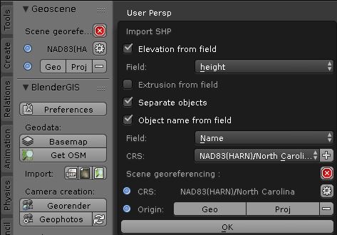
- Activate Elevation from field and in field panel select height
- Activate Separate objects
- Activate Object name from field and in field panel select Name, you should be able to see 4 the points on the surface and 4 objects added to the Outliner with the names Viewshed_1, Viewshed_2,Viewshed_3, Viewshed_4
- Select OK
 Blender Gis shape import dialogue Blender Gis shape import dialogue |
|---|
Python editor
import bpy
import os
filePath = os.path.dirname(bpy.path.abspath("//"))
fileName = os.path.join(filePath,'vpoints.shp')
bpy.ops.importgis.shapefile(filepath=fileName, fieldElevName="height", fieldObjName='Name', separateObjects=True, shpCRS='EPSG:3358')
Creating viewpoint markers
Imported points are 2D vectors that cannot be rendered as they don't have actual surfaces. Now we create 4 small spheres and match their location with the imported points to visualize observer locations in 3D.
GUI
- To create spheres on the viewpoint location:
- Go to 3D Viewport’s bottom header ‣ Add ‣ Mesh ‣ UV sphere. The Add UV sphere dialogue will open on the left side of the Toolbar. Set the Size parameter to 3.000
- Select Sphere object (by clicking on it in Outliner) and press ctrl+c , ctrl+v to make a copy of the object, you should see the Sphere.001 in the outline. Make 3 copies of the sphere.
- In the outliner rename the sphere objects to Sphere1, Sphere2, ... , Sphere4. You can do that by clicking on the object name.
- From Outliner select the object Viewshed_1
- Go to Properties Editor ‣ Object ‣ Transform ‣ Location to retrieve the viewshed point’s coordinates (X,Y,Z)
- To move each of the 4 spheres to the corresponding viewshed location:
- Copy and paste the retrieved coordinates from Viewshed_1 into the location parameters for Sphere1
- Add 2.0 extra units to the Z parameter (only for Location) to raise the spheres above the ground
- Repeat this process for each Viewshed and each Sphere
- You should now have 4 spheres aligned on the imported viewshed points.
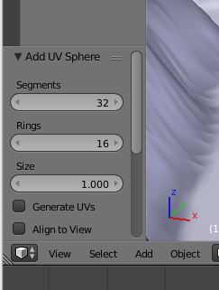 UV Sphere toolbar UV Sphere toolbar |
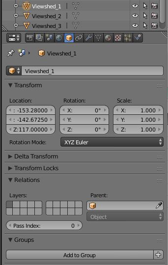 Object transform panel in properties editor Object transform panel in properties editor |
|---|
Python editor
import bpy
# get viewpoint objects create a sphere using their X,Y and Z+2 coordinates
for obj in bpy.data.objects:
    if "Viewshed" in obj.name:
        bpy.ops.mesh.primitive_uv_sphere_add(size=3.0, location=(obj.location[0],obj.location[1],obj.location[2]+2))
        sphere = bpy.context.active_object
        # rename the sphere
        sphere.name = "Sphere" + obj.name[-2:]
 4 spheres representing observation points 4 spheres representing observation points |
|---|
Generating 4 copies of the surface and viewpoint spheres
In this step we create 3 additional copies of the surface model and move each of the viewpoint spheres to the
corresponding surface.
GUI
- Select DSM object and press
ctrl+c,ctrl+vto make a copy of the object , you should see the object example1_dsm.001 in the outliner - Select object example1_dsm001
- go to Properties Editor ‣ Object (cube icon)
- In the Transform panel ‣ Delta Transform ‣ X: type 750 to move the duplicated surface 750 meters to the east
- Create another copy of the DSM , put -750 for Y parameter to move the duplicate surface 750 meters to the south
- Create another copy of the DSM, put 750 for X parameter and -750 in Y parameter. The final model should look like figure
- Repeat the same procedure for the 4 Spheres (starting from Sphere 1) so each of them are moved to one of the surface.
Python editor
import bpy

for ob in bpy.data.objects:
    ob.select = False
obj = bpy.data.objects["example1_dsm"]
obj.name = "example1_dsm1"
obj.select = True

# create and rename 3 replicates of DSM, and move spheres to create 4 DSMs and spheres
bpy.ops.object.duplicate_move(OBJECT_OT_duplicate={"mode":'TRANSLATION'}, TRANSFORM_OT_translate={"value":(750, 0, 0 )})
bpy.data.objects ["example1_dsm1.001"].name = "example1_dsm2"
sphere2Obj = bpy.data.objects ["Sphere_2"]
loc = sphere2Obj.location
sphere2Obj.location = (loc[0]+750, loc[1], loc[2])

bpy.ops.object.duplicate_move(OBJECT_OT_duplicate={"mode":'TRANSLATION'}, TRANSFORM_OT_translate={"value":(0, -750, 0 )})
bpy.data.objects ["example1_dsm2.001"].name = "example1_dsm3"
sphere3Obj = bpy.data.objects ["Sphere_3"]
loc = sphere3Obj.location
sphere3Obj.location = (loc[0]+750, loc[1]-750, loc[2])

bpy.ops.object.duplicate_move(OBJECT_OT_duplicate={"mode":'TRANSLATION'}, TRANSFORM_OT_translate={"value":(-750, 0, 0 )})
bpy.data.objects ["example1_dsm3.001"].name  = "example1_dsm4"
sphere4Obj = bpy.data.objects ["Sphere_4"]
loc = sphere4Obj.location
sphere4Obj.location = (loc[0],loc[1]-750, loc[2])
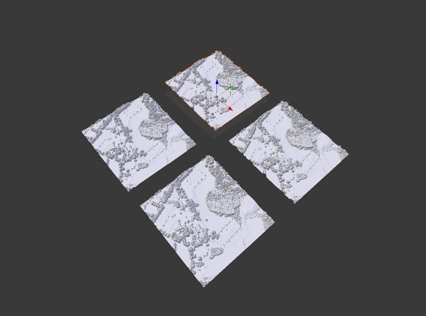 Replicated models Replicated models |
|---|
V. Shading the scene
Now we will create a mixed material to combine Orthophoto and viewshed maps. We will use emission shaders to show viewsheds as glowing surfaces. For doing that we have created grayscale viewshed maps with black background, emission shader assigns greater light emission power to the lighter pixels.
GUI
- Make sure that the Render engine is set to Cycles and 3D viewport Shading is set to Material
- Change the bottom editor panel to Node editor. This can be done by simply changing the Editor Type selector (bottom left hand side of the window).
- Select the first DSM object "example_dsm1"
- Go to Properties tab ‣ Material Press + New button to add material
- Rename the Material to "Viewshed1"
- Expand the Surface panel and click on the gray square shaped icon on the right side of the Surface parameter to see a popup window with texture parameters. Select Mix Shader . You should be able to see two Shaders added below the mix shader.
- Click on the first shader and select Emission from the dropdown list
- Click on the radio button on the right side of the color field ‣ texture ‣ Image texture
- Click on Open and load "viewshed_1_1.png". You should be able to see the viewshed draped on the DSM surface
- Change the Strength slider to 1.8 to increase the viewshed's emission power
- Click on the second shader and select Diffuse BSDF from the dropdown list
- Click on the radio button on the right side of the color field ‣ texture ‣ Image texture
- Click on Open and load "ortho.png". You should be able to see the viewshed draped on the DSM surface
Now notice how the material logic and workflow is represented in Node editor. You can play with each of the individual nodes ,the links between them and the values.
- Play with the Fac slider on the Mix shader node to adjust the mixture level
- To repeat the shading procedure for the other 3 objects using "Viewshed_2_1.png", "Viewshed_3_1.png", "Viewshed_4_1.png"
- Select the Surface object and Go to Properties tab ‣ Material Press on whirpool shaped button (next to new botton) to browse and load "Viewshed 1" matarial. Make a new copy of the material by pressing the number button on the left side of the material name field. Rename the new material to "Viewshed 2".
- Now either from the Node editor or in the Material tab change the emmission texture to "viewshed_2_1.png"
- Repeat the same procedure for two other surfaces.
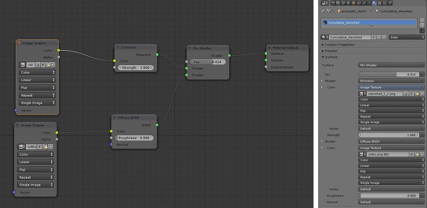 Node editor and Properties panel Node editor and Properties panel |
|---|
Python editor
import bpy
import os
filePath = os.path.dirname(bpy.path.abspath("//"))
ortho = os.path.join(filePath, 'ortho.png')

for obj in bpy.data.objects:
    if "dsm" in obj.name :
        obj.select = True
        fileName = "viewshed_{0}_1.png".format(obj.name[-1:])
        matName = os.path.join(filePath, fileName)
# Create a new material and assign it to the DSM object # 3

        mat = (bpy.data.materials.get(matName) or
               bpy.data.materials.new(matName))

        obj.data.materials.append(mat)

        # Get material tree , nodes and links #
        mat.use_nodes = True
        node_tree = mat.node_tree
        nodes = node_tree.nodes
        links = node_tree.links
        for node in nodes:
            nodes.remove(node)
        diffuseNode = node_tree.nodes.new("ShaderNodeBsdfDiffuse")
        diffuseNode.location = (300,400)
        #diffuseNode = nodes["Diffuse BSDF"]

        # Add a new texture for viewshed #
        viewshedNode = node_tree.nodes.new("ShaderNodeTexImage")
        viewshedNode.select = True
        node_tree.nodes.active = viewshedNode
        viewshedNode.image = bpy.data.images.load(matName)
        viewshedNode.location = (100, 100)

        # Add a new texture for ortho #
        orthoNode = node_tree.nodes.new("ShaderNodeTexImage")
        orthoNode.select = True
        node_tree.nodes.active = orthoNode
        orthoNode.image = bpy.data.images.load(ortho)
        orthoNode.location = (100, 400)
        # Add a new mixshader node and link it to the diffuse color node#

        mixShaderNode = node_tree.nodes.new("ShaderNodeMixShader")
        mixShaderNode.location = (600, 250)
        mixShaderNode.inputs["Fac"].default_value = .7
        emissionNode = node_tree.nodes.new("ShaderNodeEmission")
        emissionNode.location = (300, 100)
        outputNode = node_tree.nodes.new("ShaderNodeOutputMaterial")
        outputNode.location = (800, 250)
        emissionNode.inputs[1].default_value = 2

        links.new (viewshedNode.outputs["Color"], emissionNode.inputs["Color"])
        links.new (orthoNode.outputs["Color"], diffuseNode.inputs["Color"])
        links.new (emissionNode.outputs["Emission"], mixShaderNode.inputs[2])
        links.new (diffuseNode.outputs["BSDF"], mixShaderNode.inputs[1])
        links.new (mixShaderNode.outputs["Shader"], outputNode.inputs["Surface"])
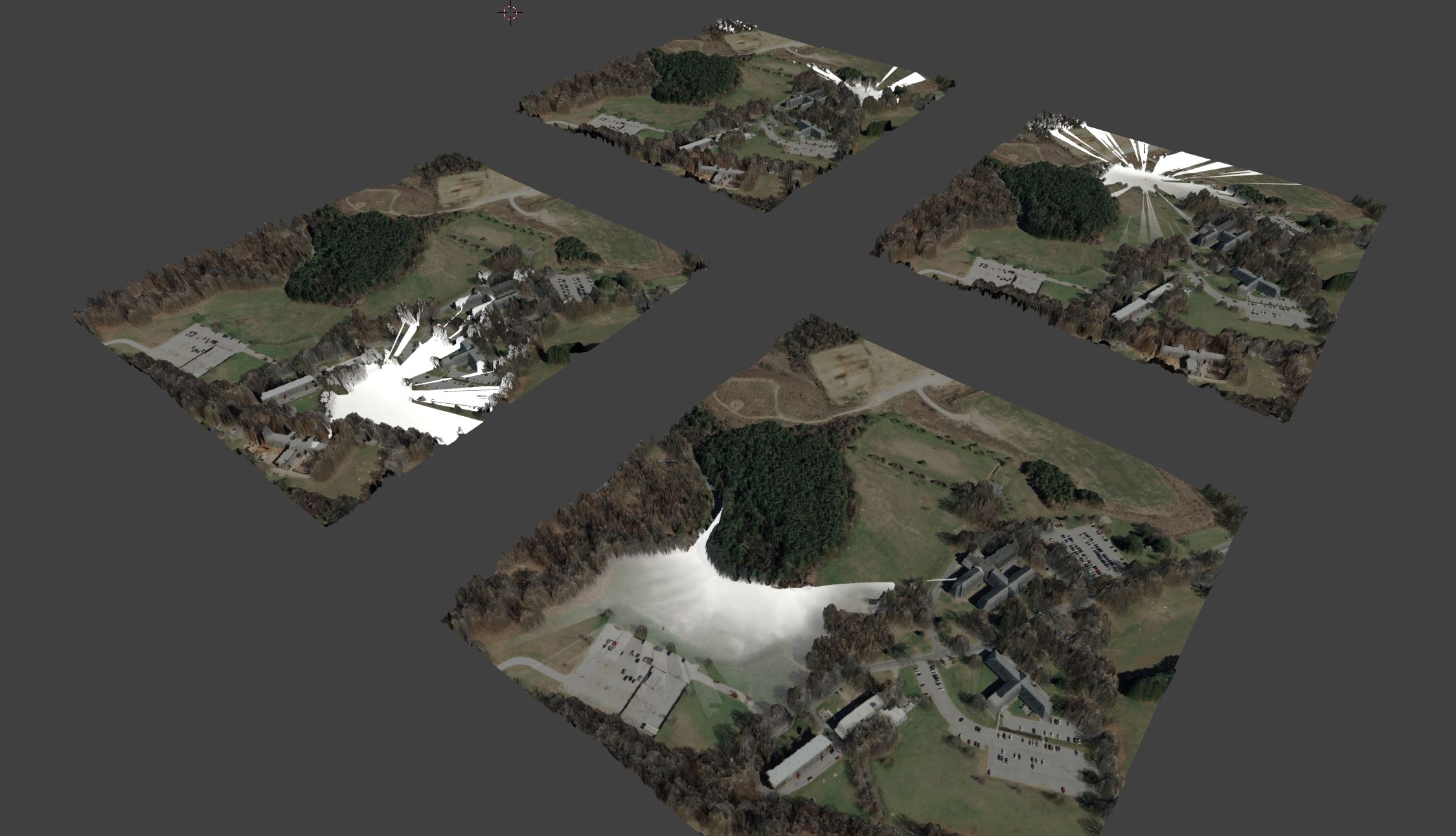 Viewshed and Orthophoto draped on DSM surface using Mix shader Viewshed and Orthophoto draped on DSM surface using Mix shader |
|---|
Shading Viewpoints
Now follow the same workflow to shade viewpoint spheres but this time only use diffuse node (Diffuse BSDF) a with solid orange color.
‣ GUI
- Select the first sphere, create a new material using Diffuse BSDF
- Change the surface color to orange
- Load the material in all sphere objects
import bpy
for obj in bpy.data.objects:
    if "Sphere" in obj.name:
        obj.select = True
        matName = "sphere"
    # Create a new material and assign it to the DSM object # 3
        mat = (bpy.data.materials.get(matName) or
               bpy.data.materials.new(matName))
        obj.data.materials.append(mat)
        # Get material tree , nodes and links #
        mat.use_nodes = True
        node_tree = mat.node_tree
        nodes = node_tree.nodes
        links = node_tree.links
        nodes[1].inputs[0].default_value = (.8, .3, 0, 1)
        obj.select = False
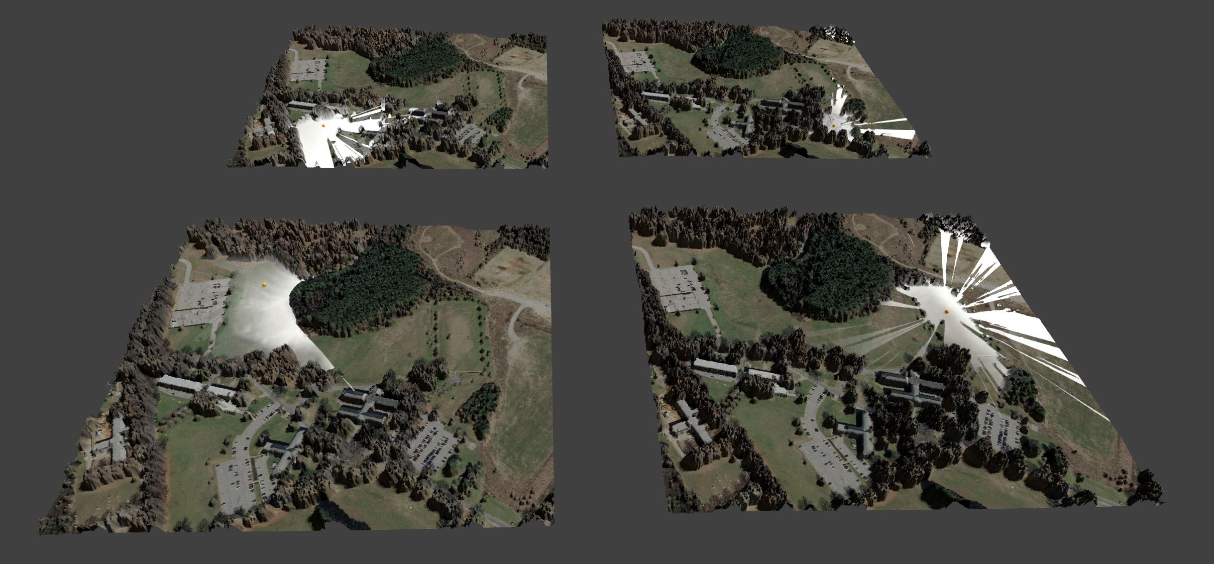 Viewport render of the viewshed Viewport render of the viewshed |
|---|
VI. modeling made easy
Now lets try to run the entire procedure with a python file using Text editor and Python console
‣ GUI
- From top header goto file‣ New to Open a fresh copy of Blender
- Save the blender file with you preferred name in the workshop directory. Note: This is an important step since your all the paths in python code are linked to that directory
- In the top header find Layout (right next to help ) and switch the layout to Scripting The scripting layout includes : a Text editor(left), a Python Console (bottom) and 3D view (right)
- Procedure for Text editor
- In Text editor ‣ Open ‣ Go to workshop directory and find example_a.py
- Click on run script
- Procedure for Python Console
- type the following lines in the console. Note that you need to type in the workshop path in you computer in the first line.
Python Console>>>
filename = "/full/path/to/example_a.py"
exec(compile(open(filename).read(), filename, 'exec'))
Python editor
import bpy
import os

filePath = os.path.dirname(bpy.path.abspath("//"))
dsmName = os.path.join(filePath,'example1_dsm.tif')
imgPath = os.path.join(filePath,'cumulative_viewshed.png')
vpointName = os.path.join(filePath,'vpoints.shp')
ortho = os.path.join(filePath, 'ortho.png')

# Setting up the scene
if bpy.data.objects.get("Cube"):
    cube = bpy.data.objects["Cube"]
    cube.select = True
    bpy.ops.object.delete()

# change lamp type and elevation
import bpy
lamp = bpy.data.lamps["Lamp"]
lamp.type = "SUN"
lampObj = bpy.data.objects["Lamp"]
lampObj.location[2] = 1000

# Setup node editor for lamp and increase the lamp power
lamp.use_nodes = True
lamp.node_tree.nodes["Emission"].inputs[1].default_value = 6

# Set render engine to cycles
bpy.context.scene.render.engine = 'CYCLES'
bpy.ops.importgis.georaster(filepath=dsmName,
                            importMode="DEM", subdivision="subsurf",
                            rastCRS="EPSG:3358")

# Subdivision render engine to cycles
bpy.ops.object.mode_set(mode='EDIT')
bpy.ops.mesh.select_all(action='SELECT')
bpy.ops.mesh.subdivide(number_cuts=4, smoothness=0.2)
bpy.ops.object.mode_set(mode='OBJECT')

# import viewpoints
bpy.ops.importgis.shapefile(filepath=vpointName,fieldElevName="height",fieldObjName='Name',separateObjects=True,shpCRS='EPSG:3358')

# adding spheres
for obj in bpy.data.objects:
    if "Viewshed" in obj.name:
        bpy.ops.mesh.primitive_uv_sphere_add(size=3.0, location=(obj.location[0],obj.location[1],obj.location[2]+2))
        sphere = bpy.context.active_object
        # rename the sphere
        sphere.name = "Sphere" + obj.name[-2:]

for ob in bpy.data.objects:
    ob.select = False
obj = bpy.data.objects["example1_dsm"]
obj.name = "example1_dsm1"
obj.select = True

# create and rename 3 replicates of DSM, and move spheres to create 4 DSMs and spheres

bpy.ops.object.duplicate_move(OBJECT_OT_duplicate={"mode":'TRANSLATION'}, TRANSFORM_OT_translate={"value":(750, 0, 0 )})
bpy.data.objects ["example1_dsm1.001"].name = "example1_dsm2"
sphere2Obj = bpy.data.objects ["Sphere_2"]
loc = sphere2Obj.location
sphere2Obj.location = (loc[0]+750, loc[1], loc[2])

bpy.ops.object.duplicate_move(OBJECT_OT_duplicate={"mode":'TRANSLATION'}, TRANSFORM_OT_translate={"value":(0, -750, 0 )})
bpy.data.objects ["example1_dsm2.001"].name = "example1_dsm3"
sphere3Obj = bpy.data.objects ["Sphere_3"]
loc = sphere3Obj.location
sphere3Obj.location = (loc[0]+750, loc[1]-750, loc[2])

bpy.ops.object.duplicate_move(OBJECT_OT_duplicate={"mode":'TRANSLATION'}, TRANSFORM_OT_translate={"value":(-750, 0, 0 )})
bpy.data.objects ["example1_dsm3.001"].name  = "example1_dsm4"
sphere4Obj = bpy.data.objects ["Sphere_4"]
loc = sphere4Obj.location
sphere4Obj.location = (loc[0],loc[1]-750, loc[2])

# Shading Viewsheds
for obj in bpy.data.objects:
    if "dsm" in obj.name :
        obj.select = True
        fileName = "viewshed_{0}_1.png".format(obj.name[-1:])
        matName = os.path.join(filePath, fileName)
# Create a new material and assign it to the DSM object # 3

        mat = (bpy.data.materials.get(matName) or
               bpy.data.materials.new(matName))

        obj.data.materials.append(mat)

        # Get material tree , nodes and links #
        mat.use_nodes = True
        node_tree = mat.node_tree
        nodes = node_tree.nodes
        links = node_tree.links
        for node in nodes:
            nodes.remove(node)
        diffuseNode = node_tree.nodes.new("ShaderNodeBsdfDiffuse")
        diffuseNode.location = (300,400)
        #diffuseNode = nodes["Diffuse BSDF"]

        # Add a new texture for viewshed #
        viewshedNode = node_tree.nodes.new("ShaderNodeTexImage")
        viewshedNode.select = True
        node_tree.nodes.active = viewshedNode
        viewshedNode.image = bpy.data.images.load(matName)
        viewshedNode.location = (100, 100)

        # Add a new texture for ortho #
        orthoNode = node_tree.nodes.new("ShaderNodeTexImage")
        orthoNode.select = True
        node_tree.nodes.active = orthoNode
        orthoNode.image = bpy.data.images.load(ortho)
        orthoNode.location = (100, 400)
        # Add a new mixshader node and link it to the diffuse color node#

        mixShaderNode = node_tree.nodes.new("ShaderNodeMixShader")
        mixShaderNode.location = (600, 250)
        mixShaderNode.inputs["Fac"].default_value = .7
        emissionNode = node_tree.nodes.new("ShaderNodeEmission")
        emissionNode.location = (300, 100)
        outputNode = node_tree.nodes.new("ShaderNodeOutputMaterial")
        outputNode.location = (800, 250)
        emissionNode.inputs[1].default_value = 2

        links.new (viewshedNode.outputs["Color"], emissionNode.inputs["Color"])
        links.new (orthoNode.outputs["Color"], diffuseNode.inputs["Color"])
        links.new (emissionNode.outputs["Emission"], mixShaderNode.inputs[2])
        links.new (diffuseNode.outputs["BSDF"], mixShaderNode.inputs[1])
        links.new (mixShaderNode.outputs["Shader"], outputNode.inputs["Surface"])
# shading viewpoints
for obj in bpy.data.objects:
    if "Sphere" in obj.name:
        obj.select = True
        matName = "sphere"
    # Create a new material and assign it to the DSM object # 3
        mat = (bpy.data.materials.get(matName) or
               bpy.data.materials.new(matName))
        obj.data.materials.append(mat)
        # Get material tree , nodes and links #
        mat.use_nodes = True
        node_tree = mat.node_tree
        nodes = node_tree.nodes
        links = node_tree.links
        nodes[1].inputs[0].default_value = (.8, .3, 0, 1)
        obj.select = False

# Switch to shading mode
for area in bpy.context.screen.areas:
    if area.type == 'VIEW_3D':
          for space in area.spaces:
              if space.type == 'VIEW_3D':
                  space.viewport_shade = 'MATERIAL'