landscape_modeling_example - ptabriz/geodesign_with_blender GitHub Wiki
-
I. Setting up the blender Scene
-
II. Modeling the terrain
-
III. Modeling the water features
-
IV. Modeling vegetation patches
- Download and install latest version of Blender from here.
- Download and install Blender GIS addon from here. Installation guide available here.
- Download and unpack sample_data folder from here
GUI
- Run Blender and open the file "example_Landscape.blend".
- Select the default
Cubeobject in 3D viewport and delete it (right-click on the object > press delete > ok ) - Set
render engineto "Cycles". You can find it in the top header, the default is "Blender Render" - To increase the Lamp elevation and change the Lamp type to "Sun" for appropriate lighting:
- Left click on the
Lampobject inOuliner(on the right side wih objects' list) to select it - Go to
Properties editor>Object(the orange cube icon) >Transformsection > in theLocationmatrix, change the Z value to 1000 (see below figure if needed)
- Left click on the
- To change lamp type to Sun and increase the emission:
- In
Properties editor>Lamp(two icons to the right of theObjecticon) > expand theLampsection > Change lamp type to Sun - Expand the
Nodessection > Click onUse Nodesto enable modifying Sun parameters. - Set the
Strengthparameter to 6.00
- In
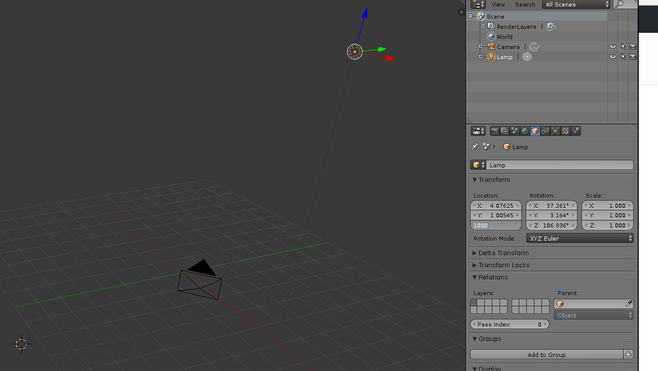 Changing the lamp elevation Changing the lamp elevation |
|---|
Python editor
import bpy
# remove the cube
cube = bpy.data.objects["Cube"]
cube.select = True
bpy.ops.object.delete()

# change lamp type and elevation
import bpy
lamp = bpy.data.lamps["Lamp"]
lamp.type = "SUN"
lampObj = bpy.data.objects["Lamp"]
lampObj.location[2] = 1000

# Setup node editor for lamp and increase the lamp power
lamp.use_nodes = True
lamp.node_tree.nodes["Emission"].inputs[1].default_value = 6

# Set render engine to cycles
bpy.context.scene.render.engine = 'CYCLES'- Download the BlenderGIS addon
- Go to
file‣user preferences(Alt + Ctrl + U) ‣Add-ons‣Install from File(bottom of the window) - Browse and select "BlenderGIS-master.zip" file
- You should be able to see the addon
3Dview: BlenderGISadded to the list. If not, type "gis" in the search bar while making sure that in theCategoriespanelAllis selected. In the search results you should be able to see3Dview: BlenderGIS. Select to load the addon. - From the bottom of the preferences window click
Save User Settingsso the addon is saved and autmatically loaded each time you open blender
Before setting up the coordinate reference system of the Blender scene and configuring the scene projection, you should know the Coordinate Reference System (CRS) and the Spatial Reference Identifier (SRID) of your project. You can get the SRID from http://epsg.io/ or spatial reference website using your CRS. The example datasets in this exercise uses a NAD83(HARN)/North Carolina CRS (SSRID EPSG: 3358)
- In BlenderGIS add-on panel (in preferences windows), select to expand the
3D View>BlenderGIS - In the preferences panel find
Spatial Reference Systemsand click on the+ Addbutton - In the add window put "3358" for
definitionand "NAD83(HARN)/North Carolina" forDescription. Then selectSave to addon preferences - Select
OKand close the User Preferences window
 Installing addon and setting up Coordinate System Installing addon and setting up Coordinate System |
|---|
Learn more about Georefencing management in Blender
Blender's default settings are set to optimize viewport rendering performance and thus transparency parameters are set to minimum. Thus, Before modeling the vegetation we adjust the Blender setting to ensure that the alpha maps are properly displayed on screen.
- In the
Blender User Preferences(Alt + Ctrl + U)>System:- In
Generalsection > adjustDPIto increase/decrease icon size based on your preferences and monitor resolution. - In
OpenGLsection > deactivateMipmaps,GPU Mipmap Generation, and16Bit Float Textures. - Set
Selectionto Automatic. - Set
Anistropic filteringto Off. - Set
Window Draw Methodto Automatic and No MultiSample. - Deactivate
Text Anti-aliasing. - In
Texturesection setTexture limit sizeto Off. - Set
Images Draw Methodto GLSL.
- In
- Click on
Save User Settingson the bottom left corner of user preferences.
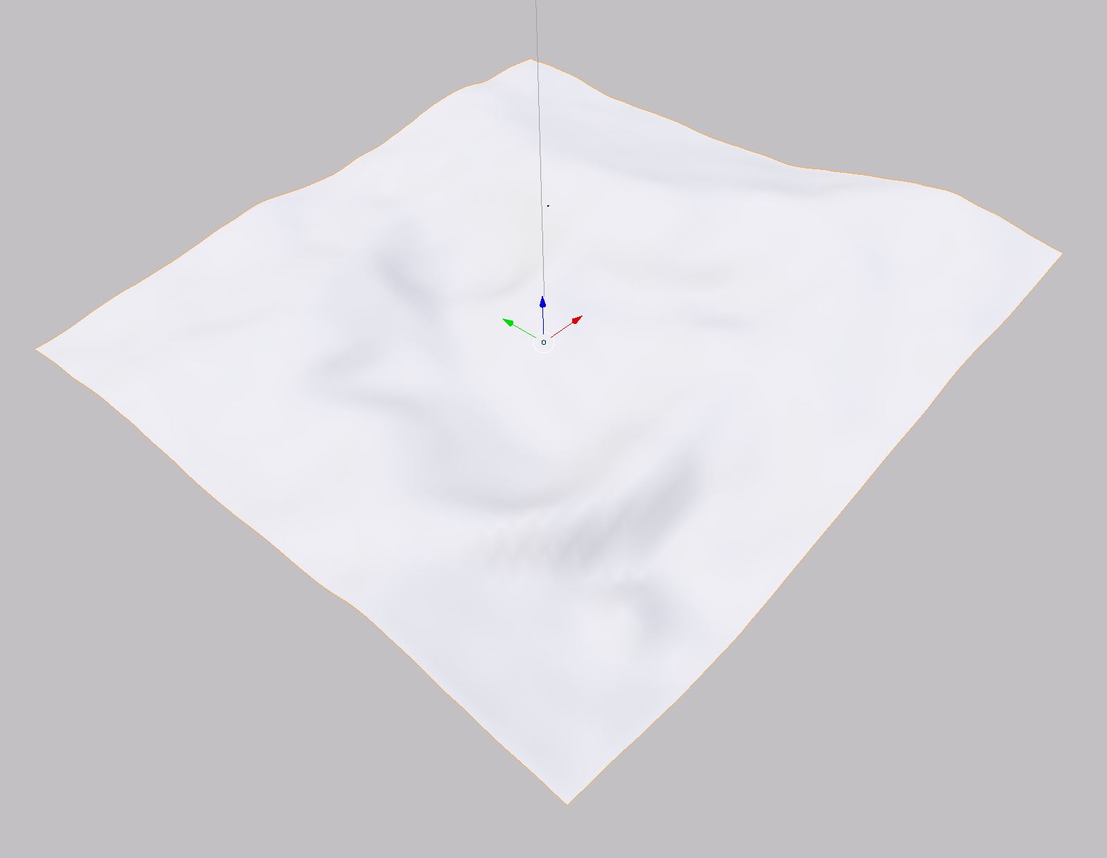
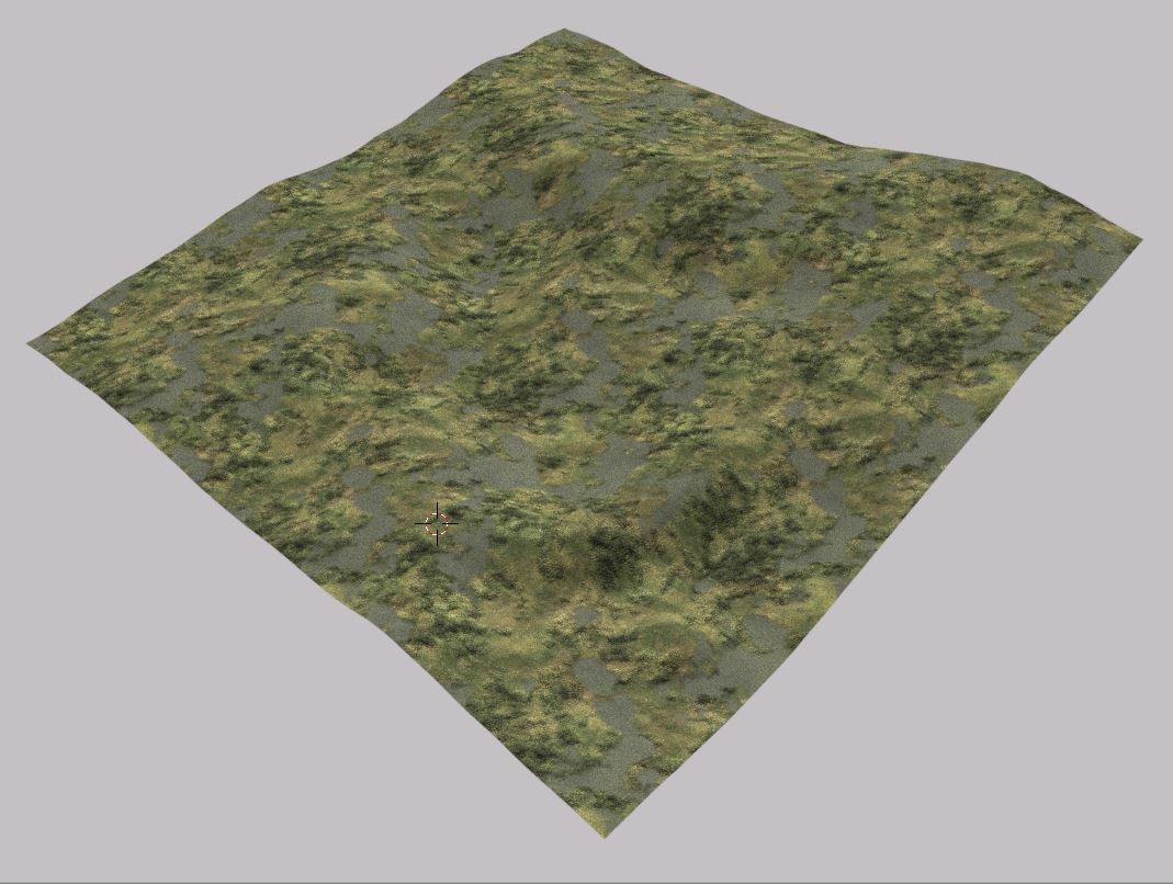 Terrain object before (left) and after the material assignment
In this example, we use BlenderGIS import function to import a terrain model with a geotiff format (.tif) and NAD1983 projection.
GUI
- Go to
file>import>Georeferenced Raster - On the bottom left side of the window find
Modeand selectAs DEM - Set
subdivisionto Subsurf and select NAD83(HARN) for georeferencing. - Browse to the Sample data folder and select 'terrain.tif'.
- Click on
Import georasteron the top right header. - If all the steps are followed correctly, you should be able to see the terrain in 3D view window.
We create a simple Terrain material using a Diffuse BSDF shader with a grass image texture.
- Change viewport display mode to
Material. - Go to
Properties tab>Material> press+ Newbutton to create a new Material. Rename the Material to Grass. - To create the diffuse Shader:
- In the
Surfacepanel notice that theDiffuse BSDFshader is selected by defaults as the surface shader. - Click on the radio button in front of the
Colorparameter to open a drop-down. From the second column, select Image Texture. - Click on
Openand navigate to the folder sample_data/textures/ > Select grass.jpg.
- In the
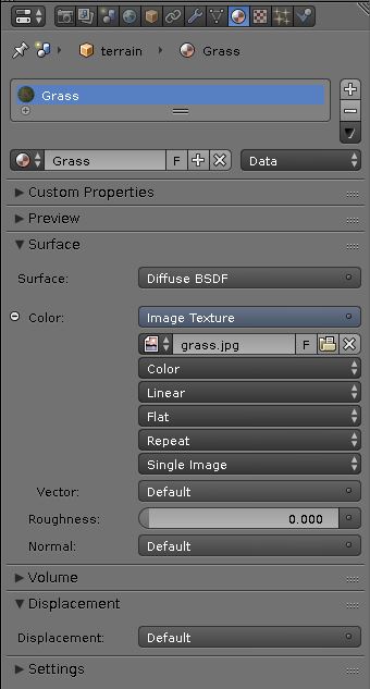
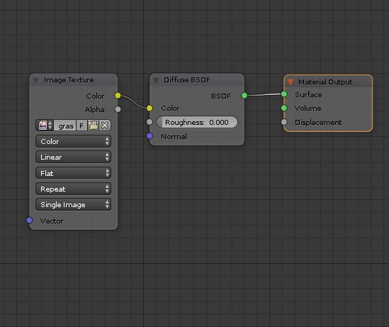 Grass material shown in properties editor (left) and node editor (right)
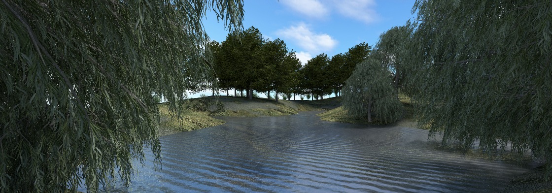
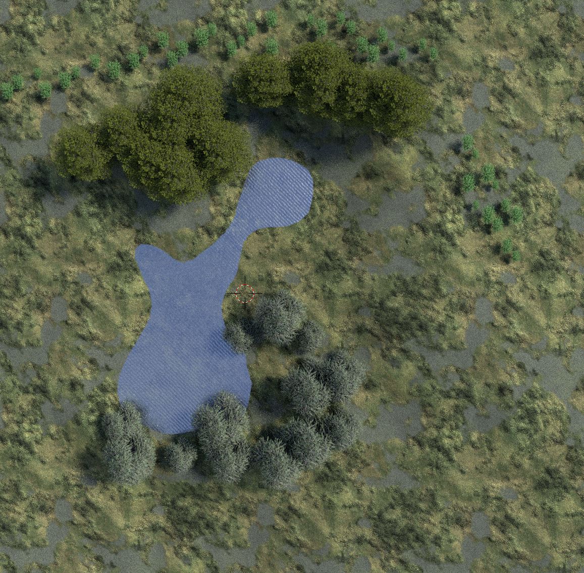
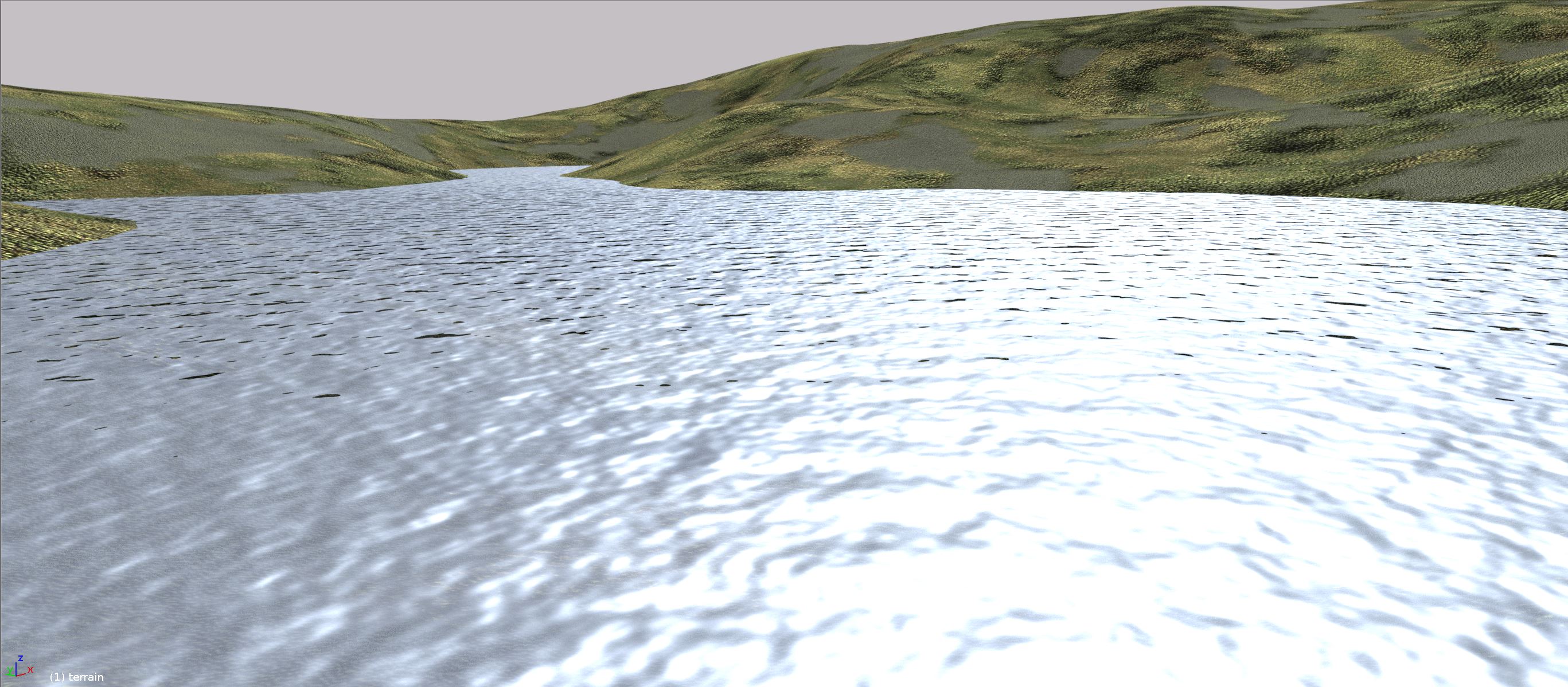 Low sample Viewport rendering of the water surface
For modeling water feature, We import a geotiff raster of a shallow pond created in and exported from Grass GIS.
- Repeat the raster import procedure described in 1.1 to import the water surface using water.tif.
- Select the Water object.
- Move the object 6 meters in minus Z direction to so that the object fits the depression.
For shading the water object, we use a more complex material that is composed of several shaders to mimic the color, reflection, wave and ripple characteristics of the actual water surface. This time we use the Node editor to create the material.
- Go to
Properties tab>Material> press+ Newbutton to create a new Material. Rename the Material to Water. - In the Node editor, bottom header use
Addmenu to add the following nodes:-
Add>Shader>Transparent BSFDto create the surface transparency. -
Add>Shader>Glossy BSDFto create the surface reflection. Set theRoughnessto 0.05 Select a pale blue for the color to represent the water color. -
Add>Texture>Wave BSDFto create the waves. SetScaleto 100 anddistortionto 0 -
Add>Texture>Noise BSDFto create the ripple. SetScaleto 300 anddistortionto 4.50 -
Add>Convertor>Mathto exaggerate the wave effect. Select Multiply with value of 5. -
Add>Convertor>Mathto exaggerate the ripple effect . Select Multiply with value of 2. -
Add>Shader>Mixto combine the surface properties (glossiness and transparency). Set theFacto 0.55 -
Add>Color>MixRGBto combine the displacement properties (wave and ripple). Set theFacto 0.5
-
- Now arrange and link the editors to acquire a node network similar to that of the figure below.
- Navigate the 3D viewport to a location close to the water and change the viewport shading mode to Render to see how the water is rendered (it should look similar to the figure below).
- Save the file.
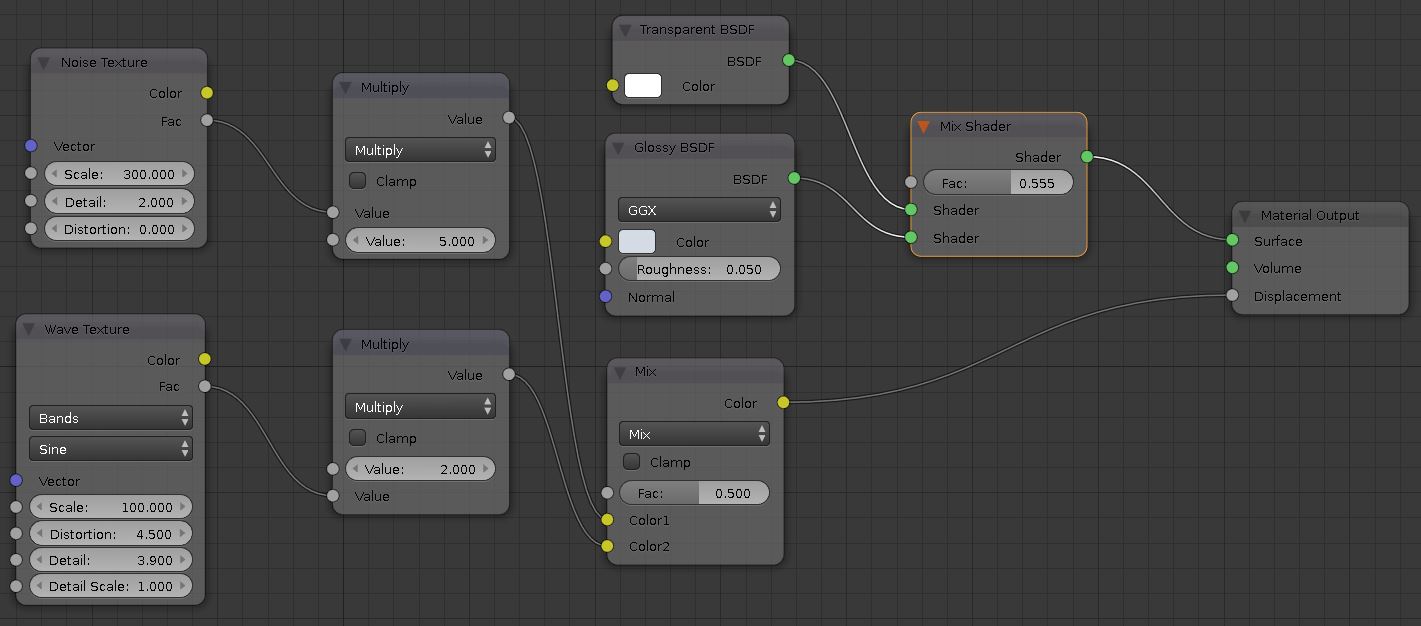
Node network of Water material
I this step, we distribute 3 types of species on the terrain, namely, American Linden, Weeping Willow, and Staghorn (shrubs). We use Xfrog tree models that are models are included in the sample_data folder as separate directories consisting of an object file (.obj), a material file (.mtl), and textures for barks and leaves. The distribution pattern (or the location of patches) of each specie is derived from GIS as a texture map (.png). Using these data we model vegetation in the following two steps.
-
Importing and shading a single model of each specie.
-
Spreading the species on the terrain based on the distribution textures.
- Linden tree object is /sample_data/EA19_American_Linden/EA15.obj and the corresponding pattern is /sample_data/patch_class1.png
- Willow tree object is /sample_data/BL15_Weeping_Willow/BL15.obj and the corresponding pattern is /sample_data/patch_class2.png
- Staghorn shrubs object is /sample_data/SH06_Spindle/SH06_3.obj and the corresponding pattern is /sample_data/patch_class3.png
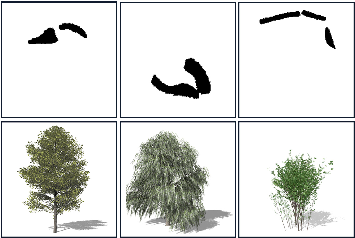 Distribution textures (top) and corresponding species (bottom). From left to right American Linden, Weeping Willow, and Staghorn.
- Open Blender and delete the default cube object.
- Change the render engine to
Cycles Render. - From
File>import> selectWavefront(.obj)> browse to sample_data/EA19_American_Linden folder and select EA19m.obj > press enter. The tree object should appear in the 3D view. - You can see that the tree object is 90 degrees rotated. To rotate it back into the vertical position:
- Right-click on the object to select and activate it.
- Go to
Propertieseditor >Object(the cube icon) > in theTransformpanelRotationsection, setXparameter to 0 .
Notice that while the leaves have material assigned to them but they are shown as rectangular surfaces with a black silhouette. To show the leaves properly we create a Mix Shader composed of a Transparent BSDF and a Diffuse BSDF. In this way we assign the transparent Black areas in the leaf image as transparent leaving the actual leaves as opaque. This technique is called Alpha mapping which is a computationally cheap way to create realistic trees without modeling the complex leaf geometry. The animation below shows how to create the material in Properties editor.

 Tree leaves before (left) and after (right) alpha mapping
- Change viewport display mode to
Material. - Go to
Properties tab>Materialand select Leaf. - Click on the
Xbutton to vacate the material slot.Note: If you click on-button you will lose the material slot that has been assigned to leaf objects. - Press
+ Newbutton to create a new Material. Rename the Material to Leaf. - To create the Mix Shader:
- From the
Surfacepanel, Surface drop down select Mix Shader - Click on the radio button in the
Facparameter to open a drop-down. From the second column, select Image Texture. - Click on
Openand navigate to the folder sample_data/EA19_American_Linden > Select EA19lef.tif .
- From the
- To create the Transparent Shader:
- From the Second
Shaderdrop down select Transparent BSDF
- From the Second
- To create the Diffuse Shader:
- From the first
Shaderdrop down select Diffuse BSDF. - Click on the radio button in the
Colorparameter to open a drop-down. From the second column, select Image Texture. - Click on
Openand navigate to the folder sample_data/EA19_American_Linden > Select EA10lef.tif .
- From the first
- To adjust the alpha display parameters:
- Go to
Settingssection and decrease theAlphaparameter inViewport Colorto 0.00.
- Go to
- Select
Viewport ShadingtoRenderto see the tree object rendered. - Assign one of the viewports to
Node Editorto explore the material node structure. - Repeat the steps a and b to import and prepare Willow and Staghorn models.
- Save the Blender file and name it tree.Blend

Alpha mapping procedure
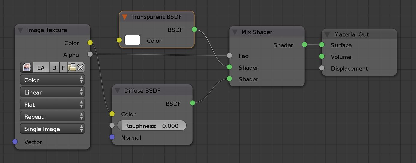
Node editor view of the tree material
In this step, we use Particle Systems Modifier to populate trees on the terrain. We use texture files that are exported from Grass GIS to delineate the location of different vegetation species class. First, we bring in the trees we created in the previous step to our landscape Blender file. To do so we append the trees to a separate layer.
- Open landscape_example.blend
- From 3D view bottom header
Layer selector > select the second slot located on the right side of the active layer. If you have a full keyboard, you can also toggle between layers using keyboard numbers.
 - Go to
File>Append> browse and find EA_19.blend > go to Objects folder and select EA19m. The tree should be now appended and visible in the scene and outliner. - Now go back to layer 1 (using bottom header or keyboard number 1) and select the terrain object.
- Select Wireframe viewport shading mode.
- Go to
Properties editor>Modifiers tab>Add modifier>Particle_system. - Type Class1 in front of the
Settingsparameter to change the setting name. - Click on the far left icon in front of the Modifier to expand and view the settings.
- Adjust the following particle settings parameters:
-
Emissionsection:- Set
Emissionnumber to 450. This is the total number of particles that will be populated on the terrain object. - Uncheck
Even distribution.
- Set
-
Rotationsection:- Activate
Rotation. - Set
Initial Rotationto ObjectY
- Activate
-
Physicssection:- Select the None option
-
Rendersection:- Activate the Object option.
- Select EA19m for the
Dupli Objectparameter. - Set the
Sizeto 1.20 and theRandom Sizeto 0.20.
-
Texturessection:- Press on the
+button to make a new texture. - Rename the texture to Texture1.
- Press the
 button to adjust the texture parameters in
 Texturestab.
- Press on the
-
- Now you are automatically routed to the Texture tab.
-
In the image section:
- Click on
Openand browse to select sample_data/patch_class1.png . You should be able to see the Trees planted according to the texture pattern.

Particle modifier settings (left) and particle texture settings (right)

Plan view of the Linden trees distributed based on the texture
- Click on
-
Instead of making new particle systems for each specie or texture, we can create a copy of an existing particle settings and just switch the emission object and texture.
- To make a copy of the particle system from the Linden tree for the Willows:
- Select terrain object.
- Add a new particle system
- Click on the dropdown menu in front of the
Settingsand select Class1. - You will see that a new icon with number 2 appears, indicating that currently two particle systems are using this settings. Click on 2 to make it a unique setting and name it Class2.
- To replace the texture image:
- Now go to the textures settings and replace the texture image with patch_class2.png found in the sample_data folder
- To replace the tree with the shrub:
- Go to
Rendersection > replace the object with BL_15
- Go to
- Change the
Emissionnumber to 1000 so that the shrubs are distributed more densely. - Clone another particle system to populate the Staghorn shrubs. Use patch_class3.png for the texture and SH06_3 as the emission object. Set the emission number to 300.
Plan view of the Linden trees distributed based on the texture
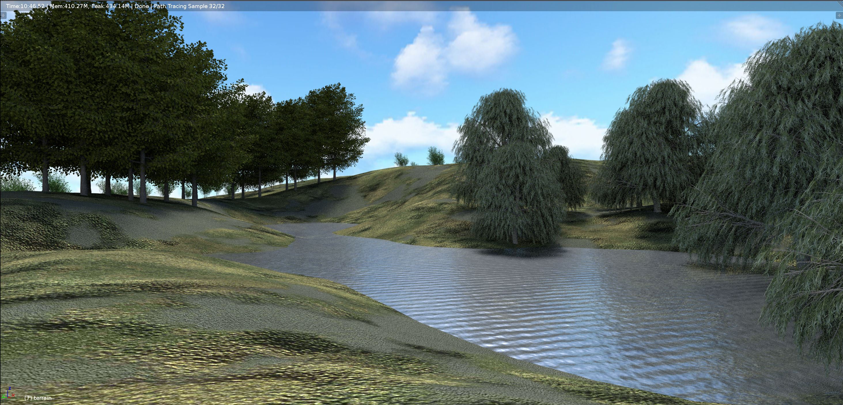
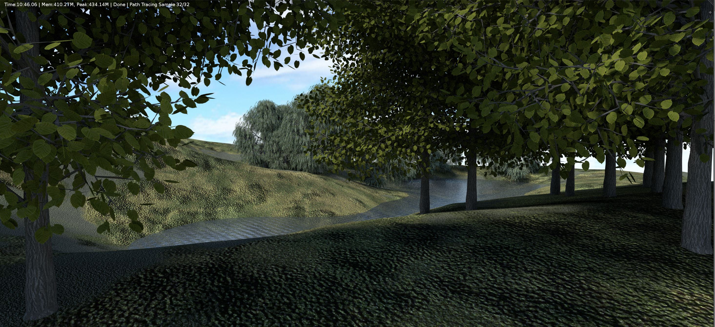
Viewport rendering of select perspectives views with 32 light sample/s