advanced_shading - ptabriz/geodesign_with_blender GitHub Wiki
I. Introduction
II. Draping the satellite imagery
III. Creating the earth surface roughness
IV. Illuminating the earth at night
V. Creating the day/night division
VI. Creating the clouds
- Download and install latest version of Blender from here.
- Download and unpack sample_data folder from here
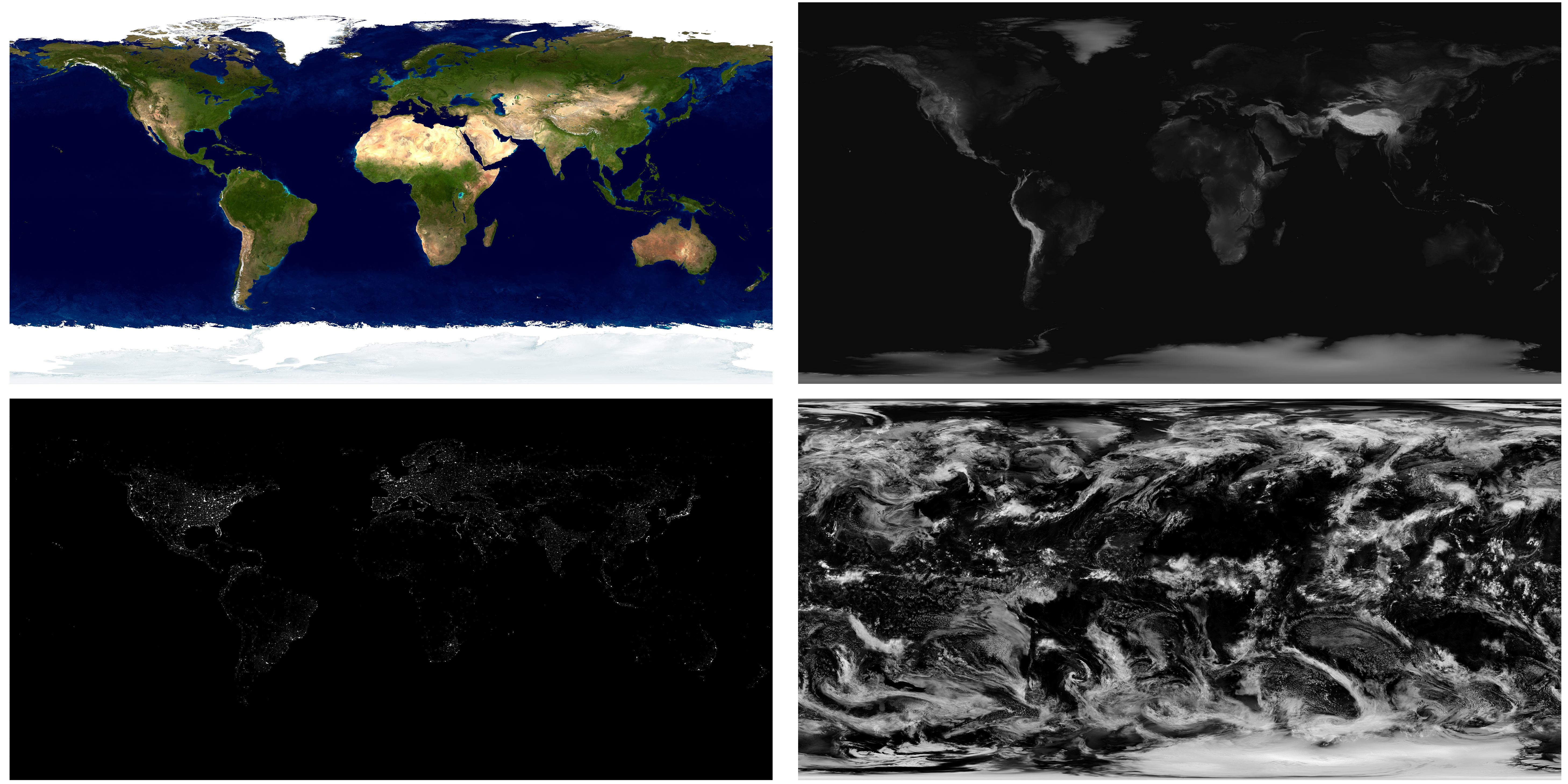 NASA satellite imagery used in this tutorial: daytime imager (above left), elevation (above right), nightime imagery (bottom left), and cloud imagery (bottom right) NASA satellite imagery used in this tutorial: daytime imager (above left), elevation (above right), nightime imagery (bottom left), and cloud imagery (bottom right) |
|---|
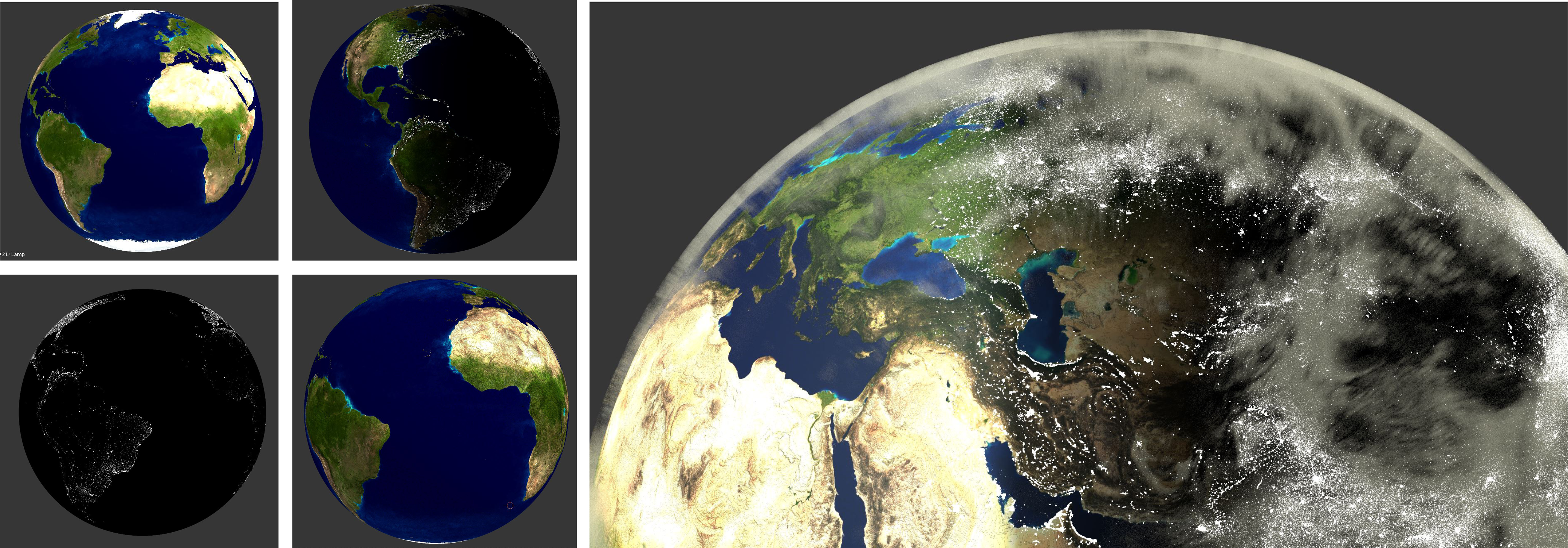
In the tutorial, we model and render earth surface and clouds using advanced shading methods available in Blender Cycle Render Engine. The tutorial will proceed in five steps each of which integrate new shaders and texture maps: 1) using daytime satellite imagery to represent the earth texture during the day; 2) using elevation map to represent surface roughness; 3) using satellite imagery to represent the nighttime texture; 4) splitting the earth surface to represent both night and day texture; 5) using the cloud imagery to represent the clouds.
We will implement all steps using the Blender's Node Editor where shaders and textures are represented as interconnecting nodes. Each step includes workflows for adding new nodes (figure below, left), linking the nodes (figure below, middle), and adjusting the parameters of each node (figure below, right). All, texture maps are retrieved from NASA satellite imagery (figure above).
 adding a new node adding a new node |
 linking two nodes linking two nodes |
 changing node parameters changing node parameters |
|---|
- Run Blender and open the file "shading_earth.blend".
- Set
render engineto "Cycles". You can find it in the top header, the default is "Blender Render" - IMPORTANT: hide the “cloud” object, so the changes to the sphere object is visible. You can hide the object by deactivating the Eye(hide) and Camera(render) icon in outliner.
- Select the Earth_sphere object (using right_click).
- Go to
Properties tab>Material> press+ Newbutton to create a new Material. Rename the Material to Globe. - Upon material creation a Diffuse Shader is automatically added which can be seen in the
Node_editor(see figure below, left).
In this step, we drape the satellite imagery as a Image Texture node connected to Diffuse BSDF shader Node. We will use Texture Coordinate node to assign the equirectangular texture to the spherical surface of the earth object. Since the globe does not have a flat surface, we need to adjust the texture dimensions so that it drapes to the globe surface. For that purpose we use a Texture Coordinate node.
-
Node additions:
- To add the satellite image as a texture image:
- In the
Node editor, bottom header click onAddmenu and go toTexture>Image Texture. - In the Texture node Click on the folder icon to browse a new image.
- Navigate to the folder sample_data > Select Albedo.jpg.
- In the
- To add the
Texture Coordinatenode:- From the
Node editor, bottom header click onAddmenu and go toInput>Texture Coordinate.
- From the
- To add the satellite image as a texture image:
-
Node links:
- Connect the Generated output to the Vector input of the
Image Texturenode. You will see that the globe image is nicely draped onto the sphere surface - Connect the
Coloroutput of the Image Texture node toColoroutput of the Diffuse node.
- Connect the Generated output to the Vector input of the
-
Node parameters:
- In the
Image Texture, third dropdown option changeFlattoSphere
- In the
-
Select
Viewport ShadingtoRenderto see the sphere object rendered.
Note: Generated option in texture coordinate node creates automatically-generated texture coordinates from the vertex positions of the mesh without deformation, keeping them sticking to the surface. see Blender Manual for more info
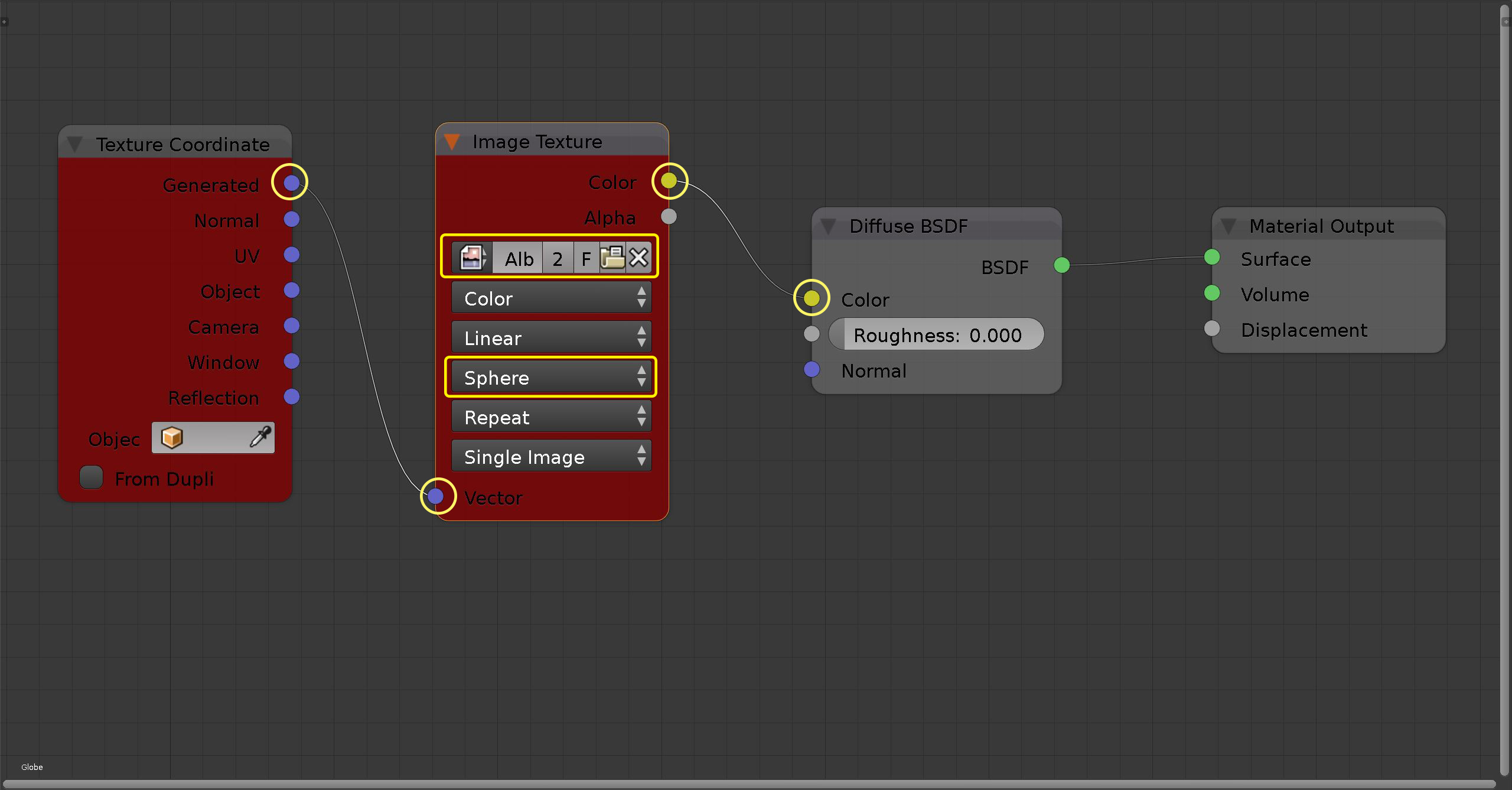 Node editor after adding the new nodes (in red) Node editor after adding the new nodes (in red) |
|---|
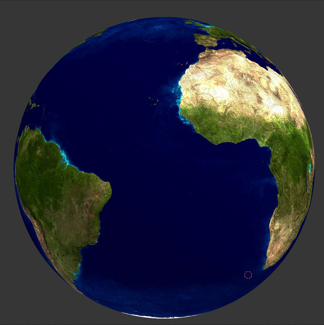
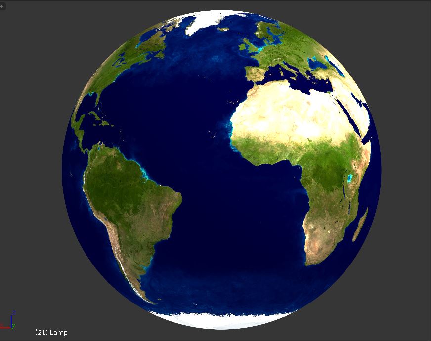 Viewport rendering of the sphere object Viewport rendering of the sphere object |
|---|
In this step, we use the elevation image map to represent the roughness of earth surface. For doing that we create a Bump node and assign the elevation map as a Height parameter using an Image texture Node.
-
Change
Viewport Shadingmode back toMaterial -
Node additions:
- To add the
BumpNode:- In the
Node editor, bottom header click onAddmenu and go toVector>Bump.
- In the
- To add the elevation image as bump map:
- Add a new
Image Texturenode (described in step II). - Click on the folder icon to browse a new image
- Navigate to the folder sample_data > Select Bump.jpg.
- Add a new
- To add the
-
Node links :
-
color output of the
Image texturenode -> height input of theBumpnode. -
Generated output of the
Texture Coordinatenode -> Vector input of theImage Texturenode. - Connect Normal output of the Bump node to Normal input of the Diffuse node.
-
color output of the
-
Node parameters :
- Set the Strength parameter of the Bump node to 1000
- In the
Image Texture, third dropdown option changeFlattoSphere
-
Set 3D Viewport Shading to
Renderto explore the new surface.
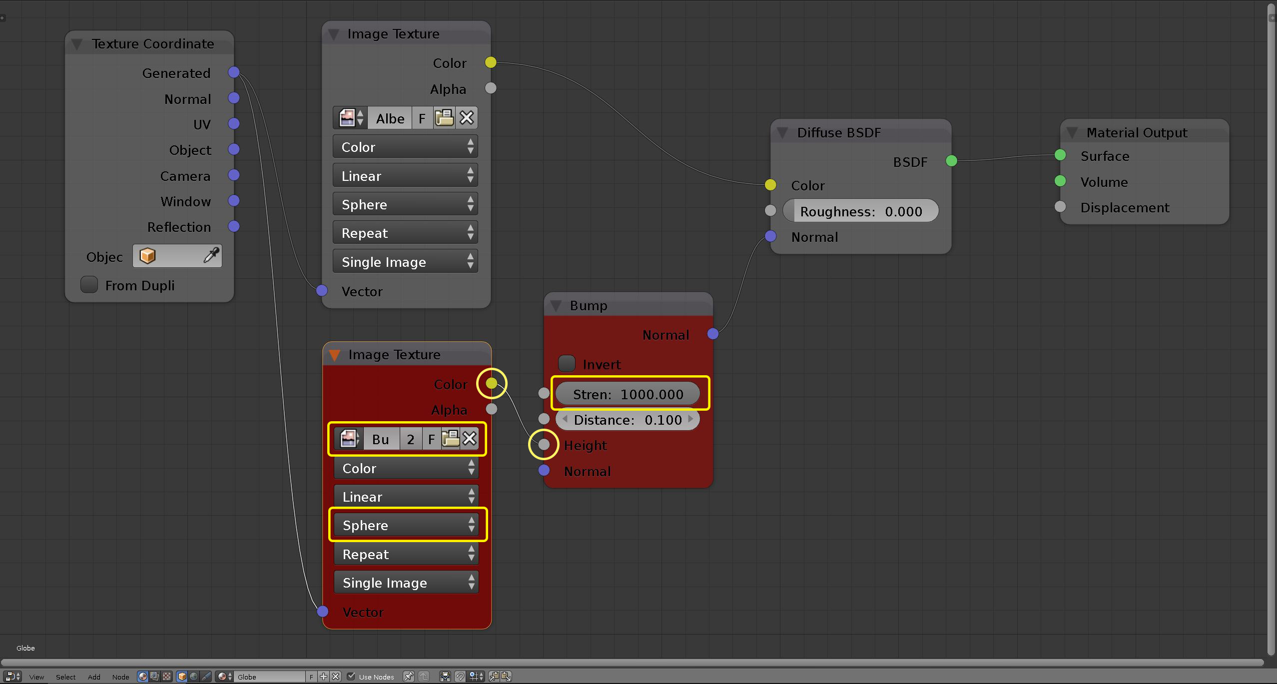 Node editor after adding the new nodes (in red) Node editor after adding the new nodes (in red) |
|---|
 Viewport rendering of the sphere object Viewport rendering of the sphere object |
|---|
In this step, we illuminate the earth using the night time satellite imagery. First, we use Emission node and Image Texture node to assign the night-time imagery. Then, we use Mix Shader node to combine the Emission and Diffuse (created in step II and III) nodes.
-
Change
Viewport Shadingmode back toMaterial -
Node additions:
- To create the
Emissionnode :- In the
Node editor, bottom header click onAddmenu and go toShader>Emission. - In the node panel, set the Strength parameter to 10
- In the
- To add the elevation image as bump map:
- Add a new
Image Texturenode (described in step II). - Click on the folder icon to browse a new image.
- Navigate to the folder sample_data > Select night_lights.png.
- In the third dropdown option of the node, change
FlattoSphere.
- Add a new
- To create the
Mix Shadernode:- From the bottom header select
Addmenu and go toShader>Mix Shader.
- From the bottom header select
- To create the
-
Node links:
-
Generated output of the
Texture Coordinatenode -> Vector input of the newImage Texturenode. -
Color output of the
Image Texture-> Color input of the newEmissionnode. -
Disconnect Surface input of the
Material Outputnode and replace it with the Shader output of theMix Shadernode. -
BSDF and Emission outputs of the Diffuse and Emission nodes -> upper and lower Shader inputs of the
Mix Shader, respectively.
-
Generated output of the
-
Node parameters:
- In the Mix shader node panel, adjust the Fac (factor) parameter to adjust the mixture level. e.g., 0.500 means that both shaders are equally mixed (figure below, left).
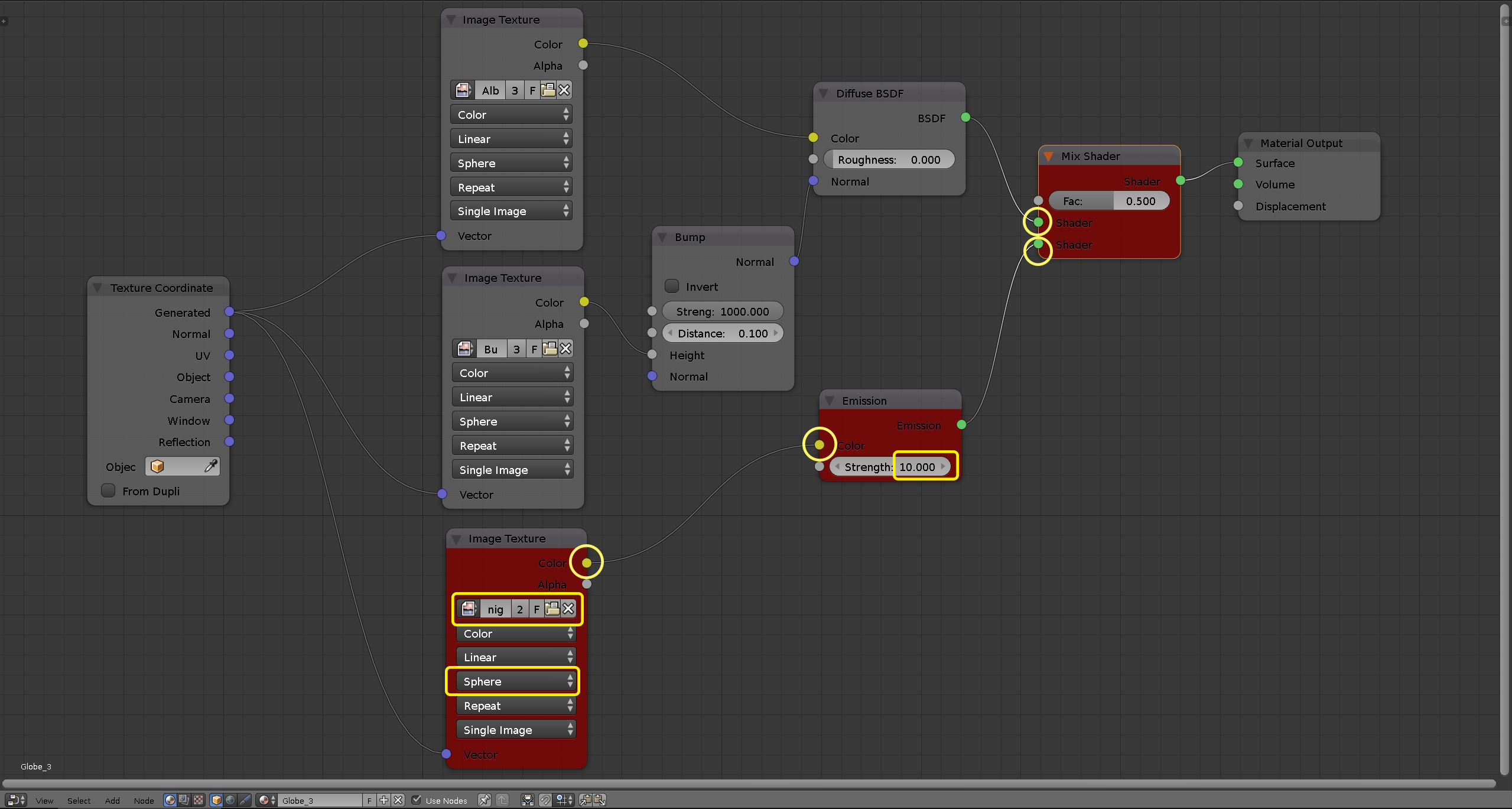 Node editor after adding the new nodes Node editor after adding the new nodes |
|---|
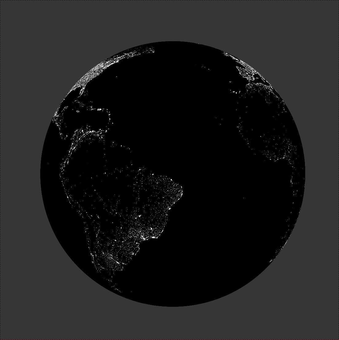 Viewport rendering of the sphere object with fac level 0 Viewport rendering of the sphere object with fac level 0 |
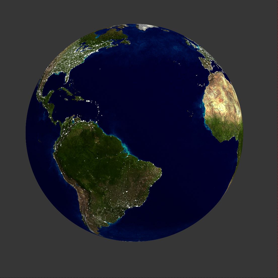 Viewport rendering of the sphere object with fac level 0.5 Viewport rendering of the sphere object with fac level 0.5 |
|---|
 Camera view (left) and perspective view (right) of the sphere object. The day/night division line is locked to the camera rotation. Camera view (left) and perspective view (right) of the sphere object. The day/night division line is locked to the camera rotation. |
|---|
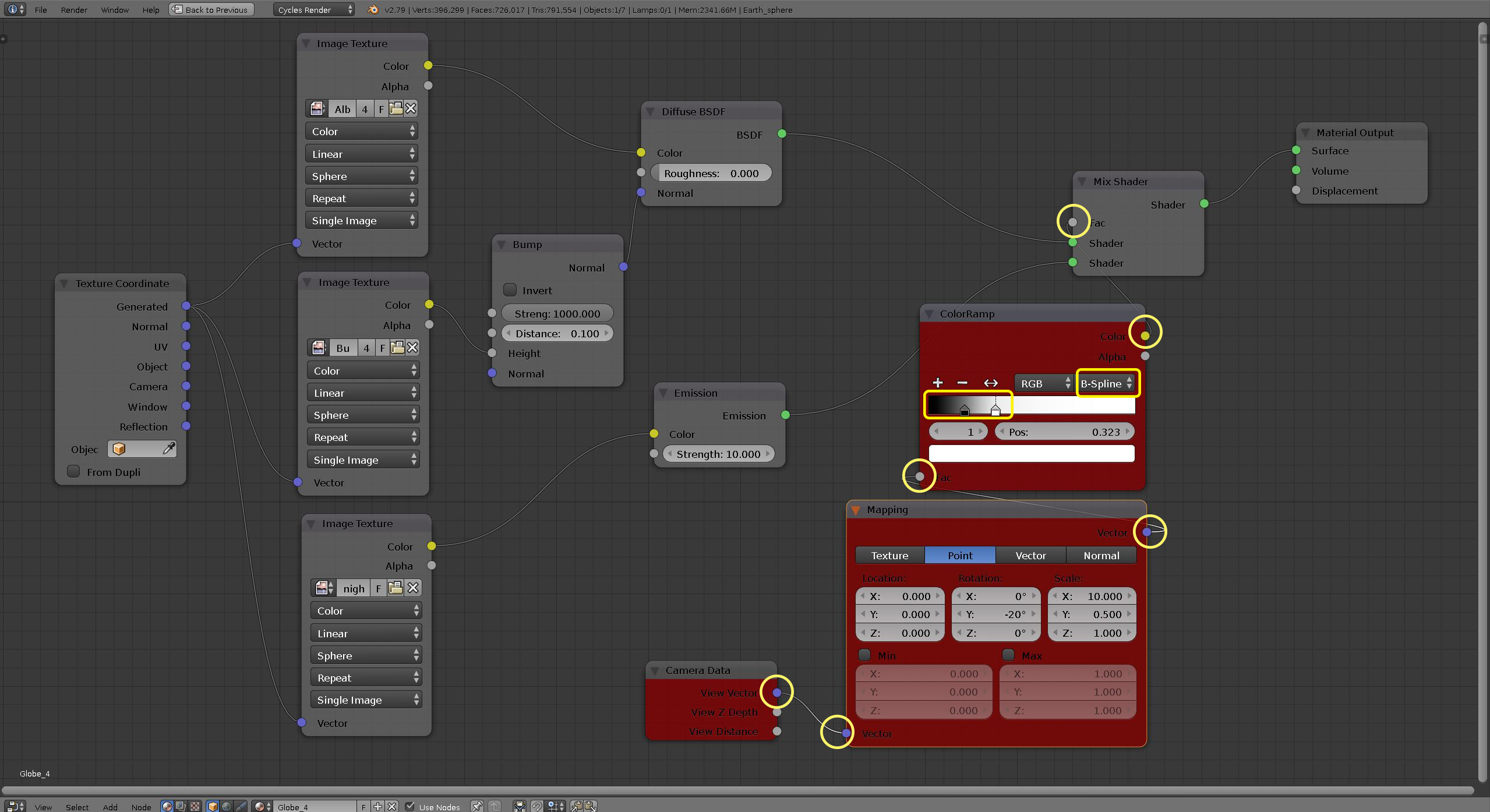
In this step we use the Color Ramp node to partly mask the earth surface to day and night portions. Then, we will link the position of the division line to the scene camera position using Camera data node so that the day/nigh division change dynamically as camera rotates around the earth. We will add extra control over the position and rotation of division line using a Mapping node. From previous step we learned how the Factor (Fac) parameter of Mix Shader node adjusts the contribution degree of each of the two shaders. The factor can also be controlled by a map such as a gradient map to control the mixture spatially.
-
Change
Viewport Shadingmode back toMaterial -
Node additions:
- To add the
Color RampMode:- From the
Node editor, bottom header click onAddmenu and go toConvertor>ColorRamp(figure below).
- From the
- To add the
Mappingnode:- From the
Node editor, bottom header click onAddmenu and go toVector>Mapping.
- From the
- To add the
Mappingnode:- From the bottom header click on
Addmenu and go toInput>Camera Data.
- From the bottom header click on
- To add the
-
Node links:
-
Color output of the
ColorRamp-> Fac input of the Mix Shader. -
Vector output of the
Mappingnode -> Fac input of the ColorRamp node. -
View Vector output of the
Camera Datanode -> Vector input of the Mapping node.
-
Color output of the
-
Node parameters:
- In the ColorRamp node:
- you can see a gradient slider with a black and white knob on the right and a left ends, respectively. Click and drag the black controller to the left and the and the white to the right until the darkness cuts through the middle of the sphere (see figure below).
- From the drop-down options right above the gradient slider change linear to spline so that the division line becomes smoother representing the twilight area.
- In the Mapping node:
- In the Scale section, change X parameter to 10, Y to 0.5 and Z to 1.0.
- In the Rotation section, change Y parameter to -20.
- In the ColorRamp node:
-
In 3D view, hold down the scroll button and drag the mouse to rotate around the sphere. You can see the darkness line moves as camera orbits around the sphere.
-
Set 3D Viewport Shading to
Renderto explore the new surface.
 Node editor after adding the new nodes Node editor after adding the new nodes |
|---|
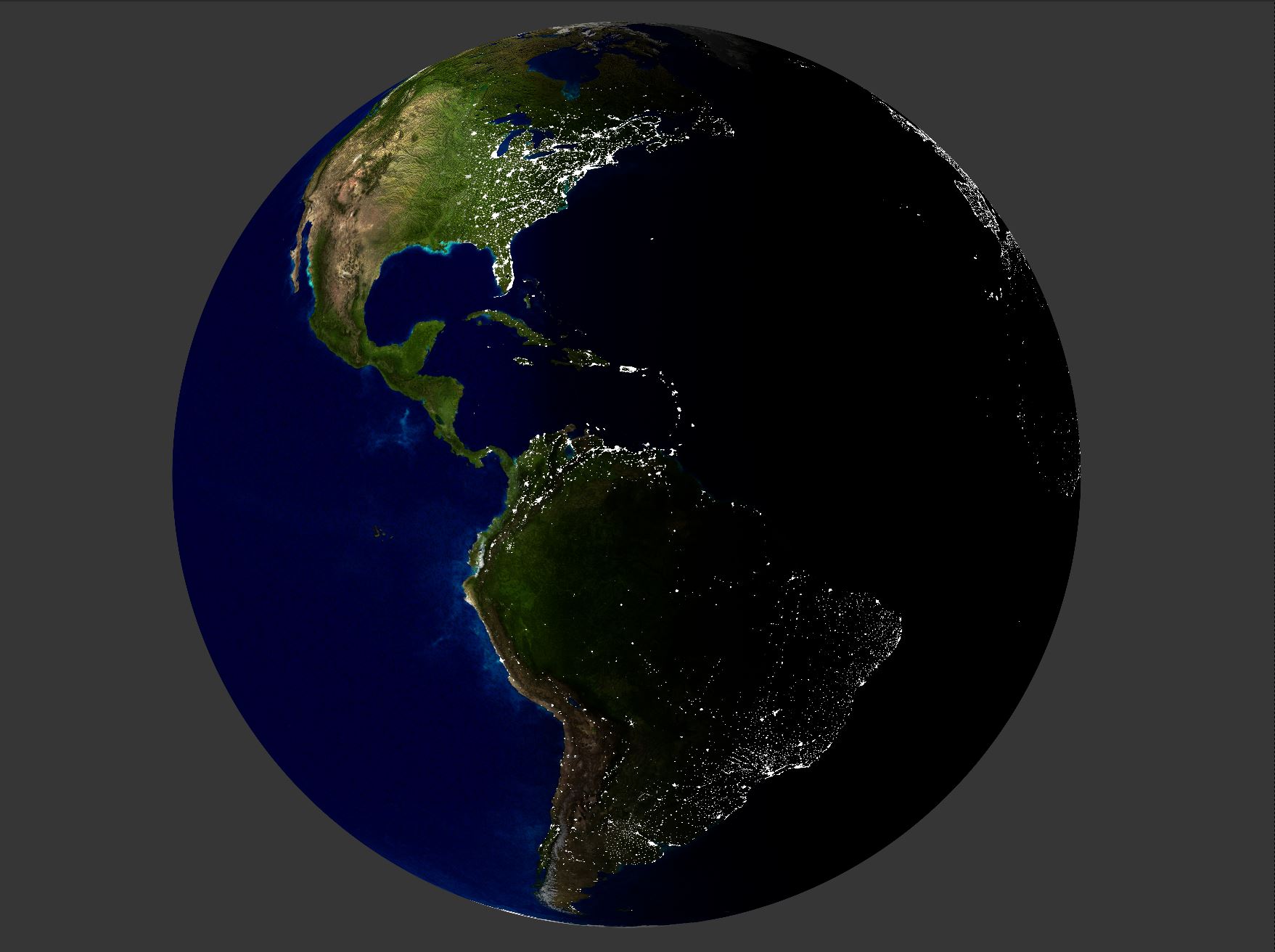 Viewport rendering of the sphere object Viewport rendering of the sphere object |
|---|
In this step, we assign Volume scatter node to a separate sphere to render the clouds. The cloud sphere is slightly larger to represent the atmosphere around earth. Similar to the first step, we use Image Texture and Texture Coordinate nodes to drape the clouds image (NASA imagery) on to the cloud sphere.
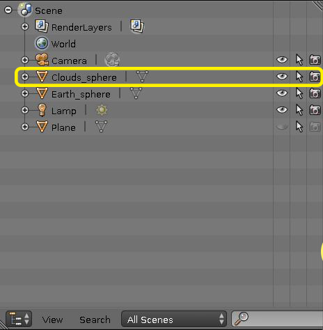 Outliner Editor showing the list of objects Outliner Editor showing the list of objects |
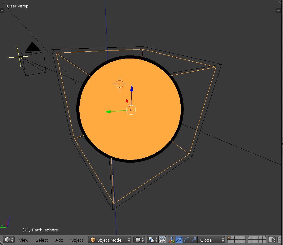 3D viewport in wireframe shading mode showing the earth sphere (highlighted in orange) inside the cloud sphere 3D viewport in wireframe shading mode showing the earth sphere (highlighted in orange) inside the cloud sphere |
|---|
-
Change
Viewport Shadingmode back toMaterial -
In the Outliner editor you can see an object called Cloud_sphere.
-
Click on the eye icon to unhide the object and the camera icon to make it renderable (figure above, left). In 3d view you should see the earth sphere object buried under the cloud sphere object which is rendered as a white solid object.
-
Add a new material and name it Clouds (see step II for creation of new material)
-
In the node editor click on
Diffuse BSDFnode and press delete to remove the node. -
Node additions:
-
To add the
Volume Scatternode:- From the
Node editor, bottom header click onAddmenu and go toShader>Volume Scatter.
- From the
-
To add the cloud image as a texture for the volume shader:
- Add a new
Image Texturenode (described in step II). - Click on the folder icon to browse a new image.
- Navigate to the folder sample_data > Select clouds.png.
- Add a new
-
To add the Texture Coordinate:
- From the
Node editor, bottom header click onAddmenu and go toInput>Texture Coordinate.
- From the
-
-
Node links:
- Generate output of the Texture Coordinate node -> Vector input of the Image Texture node.
- Color output of the Image Texture node -> Color input of the Volume Scatter.
- Volume output of the Volume Scatter node -> Volume input of the Material Output Node.
-
Node parameters:
- Image Texture node, third dropdown option of the node, change Flat to Sphere.
- In Volume Scatter node, set Density to 20 and Anistropic to 0.6.
-
Set 3D Viewport Shading to
Renderto explore the new material.
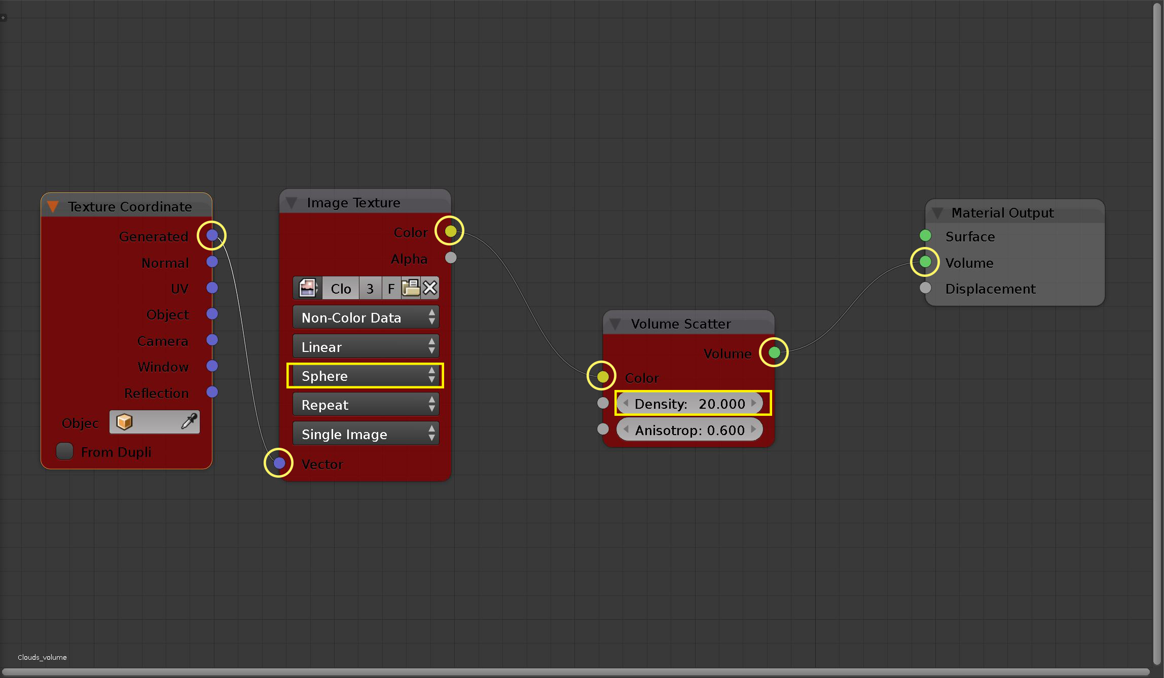 Node editor after adding the volumetric nodes Node editor after adding the volumetric nodes |
|---|
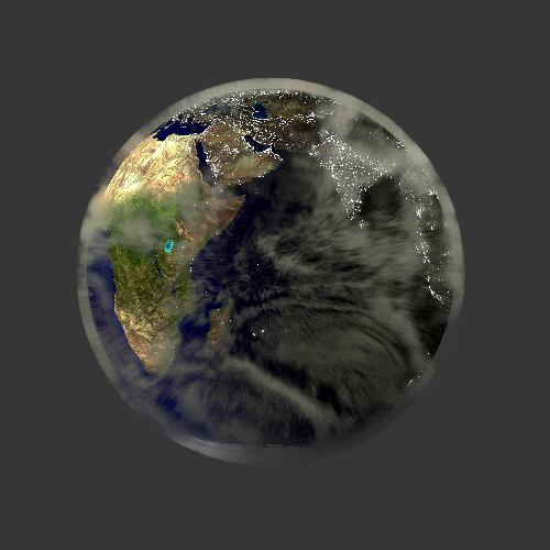 Rendering of the earth sphere object |
|---|