Pinouts for Processors and Tested Boards - pschatzmann/arduino-vs1053 GitHub Wiki
Microcontrollers
| VS1053 | Comment | ESP32 | ESP8266 | RP2040 | STM32 Blackpill | UNO R4 |
|---|---|---|---|---|---|---|
| SCK | SPI Serial Clock | 18 | D5 | D18 | PA_5 | D13 |
| (MI)SO | SPI Master Input ← Slave Output | 19 | D6 | D16 | PA_6 | D12 |
| (MO)SI | SPI Master Output → Slave Input | 23 | D7 | D19 | PA_7 | D11 |
| (X)CS | SPI Chip Select: Configured in Sketch | 5 | D1 | D17 | PA_1 | D6 |
| (X)DCS | Data Chip Select: Configured in Sketch | 16 | D0 | D9 | PA_2 | D7 |
| DREQ | Data Request: Configured in Sketch | 4 | D3 | D10 | PA_3 | D2 |
| (X)RST | Hardware Reset Pin: low=reset | 15 | RST | D11 | PA_4 | D8 |
| CS_SD | CS Pin for SD Drive | D9 | ||||
| 5V | Power Supply | 5V | 5V | VBUS | 5V | VIN |
| GND | Ground | GND | GND | GND | G | GND |
The pins marked as Configured in Sketch are just proposals that can be changed in your sketch. The setup is for for the Arduino SPI object. The RP2040 was using the implementation from Earl Phil Hower.
Breakout Boards
I was mainly using some cheap Chinese boards for my tests:
VS1003
This board is easy to use and I did not have any issues. The major drawback however is that it uses only a VS1003:
Note that the pin marked as CS is standing for XCS !
VS1053
I had plenty of issues with this board and in the beginning I did not get any sound out of it - though the SPI was working properly - but suddenly it started to work.
Note that the pin marked as CS is for the SD drive!
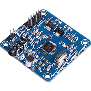
Alientek VS1053
VS1053 MP3 Shield
This board is a shield for the Arduino UNO and also contains an SD drive!