Build: DIY instructions - plan-d-io/P1-dongle GitHub Wiki
The P1 dongle is basically a ESP32 Pico D4 microcontroller with a small level shifter/inverter to interface the 3.3V ESP32 pins to the 5V P1-port of the digital meter. It can be built with off-the-shelve parts. You can also buy the recommended parts, or even a pre-assembled kit which is pretty much plug & play.
Building from scratch
If you happen to have a ESP32 Pico D4 lying around, you can easily build the P1-dongle yourself. There are multiple ways to realise the 5V-to-3.3V level shifter and inverter. Ours is based around a basic NPN transistor like the BC547 or 2N3904, a staple in most electronic home labs, and 3 resistors. The schematic is shown below.
The P1 port is transmit-only. We use ESP32 pin 21 as the receiving pin, but you can use any pin you like provided you change the pin number in the HWSERIAL.begin line in the setup() part of the code and recompile it.
The P1 port provides up to 250mA power between pin 1 (+5V) and pin 6 (Power ground). You can use this to power the ESP32 by connecting it to its 5V input pin. Note we place a low-drop Schottky diode on the 5V input to protect the ESP32 against accidental reverse polarisation, but this is completely optional.
If you want to learn more about the physical aspects of the P1-port and the DSMR data telegram, we suggest you read up on the P1 Companion Standard.
Triggering
The P1 port only sends out a data telegram when pin 2 (Data request) is asserted to the 5V level. In the above schematic, we tie pin 2 to pin 1 (+5V) so it is always asserted, resulting in the digital meter sending out a data telegram every second. If you want to control the rate of telegram requests, e.g. if you are using multiple dongles, you can use an optocoupler like shown below.
The optocoupler must source at least 4mA and maximum 10mA into pin 2 of the P1 port in order for the data telegram to be triggered. This can be achieved with a common PC817 optocoupler and the right current limiting resistors, although our production version of the P1 dongle uses a VO617A (SMD).
Using the recommended hardware
If you need to buy a ESP32 anyway, you can just as good buy the hardware we use to build pre-assembled versions. We use the M5Stack ATOM line, which is an ecosystem of prototyping modules based around a ESP32 Pico D4 microcontroller.
You will need a:
- ATOM Lite microcontroller unit
- ATOMIC DIY Proto kit
- the components to build level shifter circuit(see above)
The above components can be bought at several online retailers.
The ATOMIC DIY Proto kit is nice because it comes with a neat enclosure and fitting perfboard on which you can solder the circuit. The bundled connector only has 4 pins, but this is actually more than you need as you can combine the P1-port pins 1 (+5V) and 2 (Data request), and pins 3 (Data ground) and 6 (Power ground).
Using the DIY assembly kit
COMING SOON
If you don't want to bother with soldering components and wires on a piece of perfboard, you can also order a complete DIY kit consisting out of a ATOM Lite microcontroller and ATOMIC DIY Proto kit bundled with the components to build the level shifter and a custom PCB to solder them on.
The custom PCB features through-hole components, so it can be easily soldered even with basic soldering experience.
Because of the size of the through-hole components, the custom PCB does not feature an optocoupler. In stead, the P1 ports Data request pin is tied to the +5V line resulting in the digital meter sending a data telegram every second (see triggering).
Manufacturing your own custom PCB
As the P1-dongle is open source, the schematic and design files are provided under the /hardware folder of the main repository. Both Eagle CAD files as gerbers are provided, which you can use to manufacture your own custom PCBs at a fab of your choosing.
P1 data cable
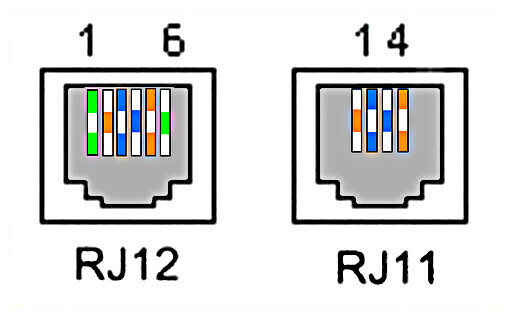
The physical form factor of the P1-port is a RJ12 6p6c connector. It resembles the ubiquitous RJ45 network connector, but it's smaller and only has 6 pins. You will need a RJ12 6p6c cable to plug the P1-dongle into the P1-portof the digital meter.
Some words of caution though. Most cables you will find in DIY shops are 6p4c, even if they claim to be RJ11/RJ12. RJ11 6p4c and RJ12 6p6c are the same form factor, but RJ11 only wires 4 of the 6 available contacts in the connector.

Telephones (the main use for RJ11) only use 4 contacts, while the P1 port uses all 6 contacts. A RJ11 6p4c cable will not work!

