Advanced: multiple dongles - plan-d-io/P1-dongle GitHub Wiki
It is possible to share the P1 port of the digital meter between the P1 dongle and other dongles (e.g. from your EV home charger). There are two ways to share the P1 port between dongles:
- Using a RJ12 splitter
- Using the downstream/slave port on the other dongle (if present)
Every method has some points to pay attention to (read below).
Using a splitter
This method works independently of the type of other dongle. You will need a RJ12 splitter and cable.
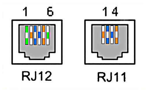
If you buy a splitter and cable, please make sure they are both RJ12 6p6c! Most splitters you will find in DIY shops are 6p4c, even if they claim to be RJ11/RJ12. RJ11 6p4c and RJ12 6p6c are the same form factor, but RJ11 only wires 4 of the 6 available contacts in the connector.

The P1 port uses all 6 contacts. Telephones (the main use for these splitters) only use 4 contacts, so that's why most splitters you will encounter will be 6p4c. A RJ11 6p4c splitter and cable will not work!
Using the downstream port
Some dongles have a downstream or slave port, which passes the P1 data telegram through. You can connect the P1 dongle to this port and it will assume it is connected to the digital meter directly. However there are some points to pay attention to (read below).
Triggering
The digital meter only transmits a data telegram if its request line is asserted high (triggered). By default, the P1 dongle asserts the request line continuously, causing the digital meter to send data telegrams at its fastest rate (1 per second).
The default request line behaviour may or may not play well with the other dongle(s). For that reason, you can configure how the P1 dongle uses the request line on the Configure digital meter page, section Triggering.
- Continuous
Default behaviour: the P1 dongle keeps the request line high to trigger a data telegram every second. - External
The P1 dongle waits for the other dongle to assert the request line, triggering a data telegram. Use this setting if the other dongle malfunctions under the Continuous setting. The update rate of the data may be impacted. - Interval
The P1 dongle raises the request line every x seconds, with x being the value set in the Trigger interval (sec) field. This might be a middle ground between Continuous and External.
Depending on the other dongle, you might need to experiment with these settings.
Power consumption
The P1 port supplies a maximum continuous current of 250mA and a peak current of 300mA. (Note: this power is provided free of charge). The P1 dongle uses 170mA when idle, with bursts up to 250mA when transmitting a telegram.
If the other dongle is also powered by the P1 port and depending on its power consumption, this might cause one or both of the dongles to brown out, meaning unexpected behaviour (reset, hanging, ...) due to a power shortage. In that case, you need to supply one of the dongles power from an external source. We recommend to first read the manual of the other dongle to find out if you can supply it external power. If not, please read below how to provide the P1 dongle with external power.
Powering the P1 dongle externally
The P1 dongle can be powered externally through its USB-C connector. You will need a power supply with a USB-C connector capable of supplying at least 250mA continuously.
Before connecting the external power source to the P1 dongle you need to perform a modification to the P1 dongle hardware. Disconnect it from the meter and place it on a flat, stable surface. Remove the microcontroller by lifting it upwards. Remove the cap covering the circuit board by pressing on both sides of the cap, releasing the inner locks and lifting the cap upwards. You now have full access to the circuit board.
Locate the two holes in the middle of the circuit board indicated by two white triangles. The triangles point to a circuit trace connecting the power supply from the digital meter to the microcontroller. You need to cut this trace with a Stanley knife or other sharp object. Just press and move the knife over the trace between the two holes a couple of times until you have made a visible carve. The trace is only 0.2mm thick.
This trace needs to be cut because otherwise the external USB-C power supply might cause an issue with the P1 port power supply, damaging the P1 dongle (and possibly the other dongle).
Place the cap and the microcontroller back on the unit. Connect the unit back to the digital meter (or splitter). Respect the polarity of the connection! The 5V connection (blue cable in the pre-assembled kit) needs to go right (top view).
Connect the USB-C power supply to the P1 dongle. It should now boot like before.
If you ever want to power the P1 dongle from the P1 port again, solder a wire bridge between the two holes in the centre of the circuit board.