Enhanced Delta - phnxdrgn536/FLSun-v400 GitHub Wiki
Delta calibration involves finding the tower endstop positions, tower angles, delta radius, and delta arm lengths. These settings control printer motion on a delta printer. Each one of these parameters has a non-obvious and non-linear impact and it is difficult to calibrate them manually. In contrast, the software calibration code can provide excellent results with just a few minutes of time. No special probing hardware is necessary.
The basic delta calibration generally does a good job of calculating delta parameters such that the nozzle is the correct distance from the bed. However, it does not attempt to calibrate X and Y dimensional accuracy. It's a good idea to perform an enhanced delta calibration to verify dimensional accuracy.
This calibration procedure requires printing a test object and measuring parts of that test object with digital calipers.
Prior to running an enhanced delta calibration one must run the basic delta calibration and save the results. Make sure there hasn't been any notable change to the printer configuration nor hardware since last performing a basic delta calibration (if unsure, rerun the basic delta calibration just prior to printing the test object described below.)
Use a slicer to generate G-Code from the calibrate_size.stl file. Slice the object using a slow speed (eg, 40mm/s). If possible, use a stiff plastic (such as PLA) for the object. The object has a diameter of 140mm.
Print the test object and wait for it to fully cool. The commands described below must be run with the same printer settings used to print the calibration object (don't run DELTA_CALIBRATE between printing and measuring, or do something that would otherwise change the printer configuration).
If possible, perform the measurements described below while the object is still attached to the print bed, but don't worry if the part detaches from the bed - just try to avoid bending the object when performing the measurements.
Start by measuring the distance between the center pillar and the pillar next to the "A" label (which should also be pointing towards the "A" tower).
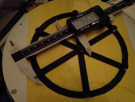
Then go counterclockwise and measure the distances between the center pillar and the other pillars (distance from center to pillar across from C label, distance from center to pillar with B label, etc.).

Enter these parameters into Klipper with a comma separated list of floating point numbers:
DELTA_ANALYZE CENTER_DISTS=<a_dist>,<far_c_dist>,<b_dist>,<far_a_dist>,<c_dist>,<far_b_dist>
Provide the values without spaces between them.
Then measure the distance between the A pillar and the pillar across from the C label.
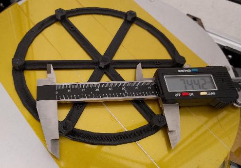
Then go counterclockwise and measure the distance between the pillar across from C to the B pillar, the distance between the B pillar and the pillar across from A, and so on.

Enter these parameters into Klipper:
DELTA_ANALYZE OUTER_DISTS=<a_to_far_c>,<far_c_to_b>,<b_to_far_a>,<far_a_to_c>,<c_to_far_b>,<far_b_to_a>
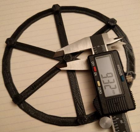
At this point it is okay to remove the object from the bed. The final measurements are of the pillars themselves. Measure the size of the center pillar along the A spoke, then the B spoke, and then the C spoke.

Enter them into Klipper:
DELTA_ANALYZE CENTER_PILLAR_WIDTHS=<a>,<b>,<c>
The final measurements are of the outer pillars. Start by measuring the distance of the A pillar along the line from A to the pillar across from C.
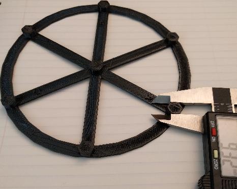
Then go counterclockwise and measure the remaining outer pillars (pillar across from C along the line to B, B pillar along the line to pillar across from A, etc.).

And enter them into Klipper:
DELTA_ANALYZE OUTER_PILLAR_WIDTHS=<a>,<far_c>,<b>,<far_a>,<c>,<far_b>
DELTA_ANALYZE SCALE=1.0
Finally, perform the enhanced delta calibration by running:
DELTA_ANALYZE CALIBRATE=extended
This command can take several minutes to complete. After completion it will calculate updated delta parameters (delta radius, tower angles, endstop positions, and arm lengths). Use the SAVE_CONFIG command to save and apply the settings:
SAVE_CONFIG
The SAVE_CONFIG command will save both the updated delta parameters and information from the distance measurements. Future DELTA_CALIBRATE commands will also utilize this distance information. Do not attempt to reenter the raw distance measurements after running SAVE_CONFIG, as this command changes the printer configuration and the raw measurements no longer apply.
-
If the V400 has good dimensional accuracy then the distance between any two pillars should be around 74mm and the width of every pillar should be around 9mm. (Specifically, the goal is for the distance between any two pillars minus the width of one of the pillars to be exactly 65mm.) Should there be a dimensional inaccuracy in the part then the DELTA_ANALYZE routine will calculate new delta parameters using both the distance measurements and the previous height measurements from the last DELTA_CALIBRATE command.
-
DELTA_ANALYZE may produce delta parameters that are surprising. For example, it may suggest arm lengths that do not match the printer's actual arm lengths. Despite this, testing has shown that DELTA_ANALYZE often produces superior results. It is believed that the calculated delta parameters are able to account for slight errors elsewhere in the hardware. For example, small differences in arm length may result in a tilt to the effector and some of that tilt may be accounted for by adjusting the arm length parameters.
Note that performing delta calibration will invalidate any previously obtained bed mesh. After performing a new delta calibration be sure to rerun Bed Mesh calibration.
If you like my work, don't hesitate to support me by buying me a 🍺 or a ☕. Thank you 🙂