Options: Outline - pcb2gcode/pcb2gcode GitHub Wiki
Options: Outline
pcb2gcode can cut around your PCB based on the edge cuts layer and separate it from the rest of the FR4.
These are the options are are useful for outline cutting:
Outline options, for cutting the PCB out of the FR4:
  --outline arg                         pcb outline polygon RS274-X .gbr
  --fill-outline [=arg(=1)] (=1)        accept a contour instead of a polygon
                                        as outline (enabled by default)
  --cutter-diameter arg                 diameter of the end mill used for
                                        cutting out the PCB
  --zcut arg                            PCB cutting depth in inches
  --cut-feed arg                        PCB cutting feed in [i/m] or [mm/m]
  --cut-vertfeed arg                    PCB vertical cutting feed in [i/m] or
                                        [mm/m]
  --cut-speed arg                       spindle rpm when cutting
  --cut-infeed arg                      maximum cutting depth; PCB may be cut
                                        in multiple passes
  --cut-front [=arg(=1)]                [DEPRECATED, use cut-side instead] cut
                                        from front side.
  --cut-side arg (=auto)                cut side; valid choices are front, back
                                        or auto (default)
  --bridges arg (=0)                    add bridges with the given width to the
                                        outline cut
  --bridgesnum arg (=2)                 specify how many bridges should be
                                        created
  --zbridges arg                        bridges height (Z-coordinates while
                                        engraving bridges, default to zsafe)
  --outline-output arg (=outline.ngc)   output file for outline
--fill-outline
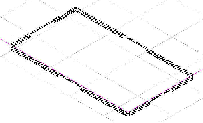
Usually gerber files specify the area of the PCB by lines and not by shapes. For example, in this file the edge cuts layer, in yellow, is thin lines surrounding the board and not a solid yellow rectangle:
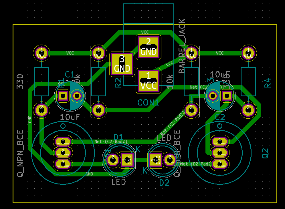
pcb2gcode can work with edge cuts that are specified as thin lines and not filled shapes by using the --fill-outline option. This requires that the lines form a closed shape! If they don't, pcb2gcode will report an error. (PCB fabs will also tell clients that this is a design error.) Because edge-cuts are usually specified this way, the default is "true". You can still make PCBs with holes in them and pcb2gcode should be able to figure it out.
With this option, the cutting happens on the centerline of the lines drawn on the edge-cuts layer. Thickness will be ignored but all edge cuts should have the same thickness.
Physical CNC options
This drawing can be useful:

--cutter-diameter: Width of the cutting bit--zcut: How deep to cut, this should be the thickness of the PCB's FR4.--cut-feed: Horizontal speed while cutting--cut-vertfeed: Vertical speed while plunging--cut-speed: Rate of rotation of the cutting bit--cut-infeed: Maximum thickness to cut for each pass. If this is less than zcut, multiple passes will be made.--cut-side: Which side, front or back, should be up while cutting. The default is "auto".
Bridges
If you cut around the PCB without any bridges, eventually the PCB will disconnect from the FR4 around it and fly off. It's better to mill around and leave bridges that connect between the PCB and the FR4 around it. Then those can be snipped with scissors or a knife to carefully disconnect from the rest of the PCB.
--bridges: The horizontal width of the bridges to make.--bridgesnum: How many bridges to make.--zbridges: How deep to cut the bridges. Bridges should be cut less deep than zcut so that some material is left to hold the board in place.
Here, four bridges were added around the shape: