Options: Milling - pcb2gcode/pcb2gcode GitHub Wiki
Options: Milling
pcb2gcode can convert gerber files into milling instructions for your CNC.
These are the options which are useful for milling:
Milling options, for milling traces into the PCB:
  --front arg                           front side RS274-X .gbr
  --back arg                            back side RS274-X .gbr
  --voronoi [=arg(=1)] (=0)             generate voronoi regions
  --offset arg (=0)                     Note: Prefer to use --mill-diameters
                                        and --milling-overlap if you just
                                        that's what you mean.  An optional
                                        offset to add to all traces, useful if
                                        the bit has a little slop that you want
                                        to keep out of the trace.
  --mill-diameters arg (=0)             Diameters of mill bits, used in the
                                        order that they are provided.
  --milling-overlap arg (=50 %)         How much to overlap milling passes,
                                        from 0% to 100% or an absolute length
  --isolation-width arg (=0)            Minimum isolation width between copper
                                        surfaces
  --extra-passes arg (=0)               [DEPRECATED] use --isolation-width
                                        instead. Specify the the number of
                                        extra isolation passes, increasing the
                                        isolation width half the tool diameter
                                        with each pass
  --pre-milling-gcode arg               custom gcode inserted before the start
                                        of milling each trace (used to activate
                                        pump or fan or laser connected to fan)
  --post-milling-gcode arg              custom gcode inserted after the end of
                                        milling each trace (used to deactivate
                                        pump or fan or laser connected to fan)
  --zwork arg                           milling depth in inches (Z-coordinate
                                        while engraving)
  --mill-feed arg                       feed while isolating in [i/m] or [mm/m]
  --mill-vertfeed arg                   vertical feed while isolating in [i/m]
                                        or [mm/m]
  --mill-infeed arg                     maximum milling depth; PCB may be cut
                                        in multiple passes
  --mill-speed arg                      spindle rpm when milling
  --mill-feed-direction arg (=0)        In which direction should all milling
                                        occur
  --invert-gerbers [=arg(=1)] (=0)      Invert polarity of front and back
                                        gerbers, causing the milling to occur
                                        inside the shapes
  --draw-gerber-lines [=arg(=1)] (=0)   Draw lines in the gerber file as just
                                        lines and not as filled in shapes
  --preserve-thermal-reliefs [=arg(=1)] (=1)
                                        generate mill paths for thermal reliefs
                                        in voronoi mode
  --front-output arg (=front.ngc)       output file for front layer
  --back-output arg (=back.ngc)         output file for back layer
--front vs --back
When you mill, you can make one-sided boards or two-sided boards. For one-sided boards, you'll usually only having milling on the back. The components are soldered to pads on the bottom and the traces there connect them:
If you want to use both then you should read about two-sided boards.
--voronoi
This is for milling voronoi regions. Voronoi milling mills along the line dividing between traces. This minimizes the amount of milling needed. If you don't mind the traces having different shapes then this can decrease the milling time.
--mill-diameters (prefer this instead of the old --offset)
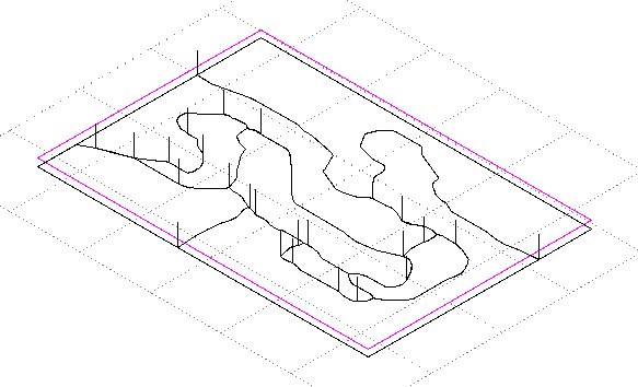
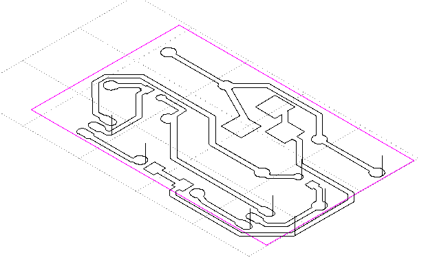
This is the diameters of the milling bits. If you specify more than one, the first milling bit will be used only where it fits. Each successive milling bit will be used only where the previous milling didn't already clear away a path. The final milling bit will always isolate all traces, even if it means potentially milling into the trace itself. If this happens, a "contentions" error will be displayed and an SVG file with the areas in contention marked will be made.
In the example above, the milling bit wasn't able to get into the sharp corner. Specifying a second milling bit fixes that. Notice how the milling happens near the corner and doesn't redo the already milled sections from the previous image:

--milling-overlap
This is how much to overlap when there is more than pass needed. The default is 50%. It can be specified as a percentage of the milling diameter or as a constant width, in mm or thou for example.
--isolation-width (prefer this instead of the old --extra-passes)
This is how thick around each trace to clear out the copper. Here's an example where the milling bit's diameter wasn't enough to clear out all the isolation-width in 1 pass, so it made 2:

--pre-milling-gcode and --post-milling-gcode
This lets you insert any text you want right before and after milling. This can be useful for turning a fan or laser on or off, for example, if you're using pcb2gcode with a laser to burn away an area.
--zwork
This is the depth at which to mill for milling traces. It ought to be below the surface of the board, so it's negative. If you use autolevelling, this height is adjusted based on the probed values.
--mill-feed and --mill-vertfeed and --mill-speed and --mill-infeed
This set the options for the motion of the mill. The mill-feed is how fast to move horizontally through the material and the mill-vertfeed is how fast to move down vertically. Up movements are done at full speed (G0). The mill-speed is the rate of rotation of the milling bit. The mill-infeed specifies how deep to make each pass of the milling. If the --zwork specifies more milling than the mill-infeed then milling will be done in multiple passes of increasing depth.
--mill-feed-direction
This sets the direction in which milling will occur. The default is "any" but "climb" and "conventional" are available. You can read more about "climb" vs "conventional". If you find that when you mill, one side of the milled line has less burrs than the other, you can use this setting to choose the direction in milling. This also affects the direction of milldrilling holes.
--invert-gerbers
Sometimes you want to reverse the polarity of the input gerbers and mill inside areas instead of outside. For example, in this case. This option will invert all gerbers so that milling will happen inside and not outside. Combined with a high isolation-width, this will potentially mill out all the insides of each shape.
--draw-gerber-lines
If you want, you can use this option to draw the silk layer on to your board. It will treat drawn lines not as traces to be milled around but instead as lines to be milled. You could use this with a very small point to etch gerber lines into the non-plated side of a one-sided board. Or you could attach a pen to your CNC machine to draw the silk layer, either directly on to the PCB or on to a sticker to apply later. For example, this silk layer:
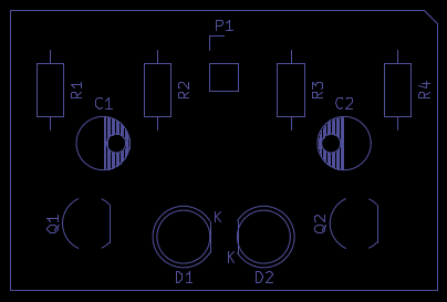
Becomes:
--preserve-thermal-reliefs
This only has effect if --voronoi is set. pcb2gcode will try to identify thermal reliefs and mill them. The default is "true" and this can be left alone. (pcb2gcode guesses that any hole in a shape that doesn't have a trace inside of it is perhaps a thermal hole. In any case, this extra milling is always safe.)