Sonoff Basic - pauloromeira/Sonoff-Tasmota GitHub Wiki
- Itead Product Page: http://sonoff.itead.cc/en/products/sonoff/sonoff-basic
- Itead Shop: https://www.itead.cc/sonoff-wifi-wireless-switch.html
- Itead Wiki: https://www.itead.cc/wiki/Sonoff
Serial Connection
Please see the Hardware Preparation page for general instructions.
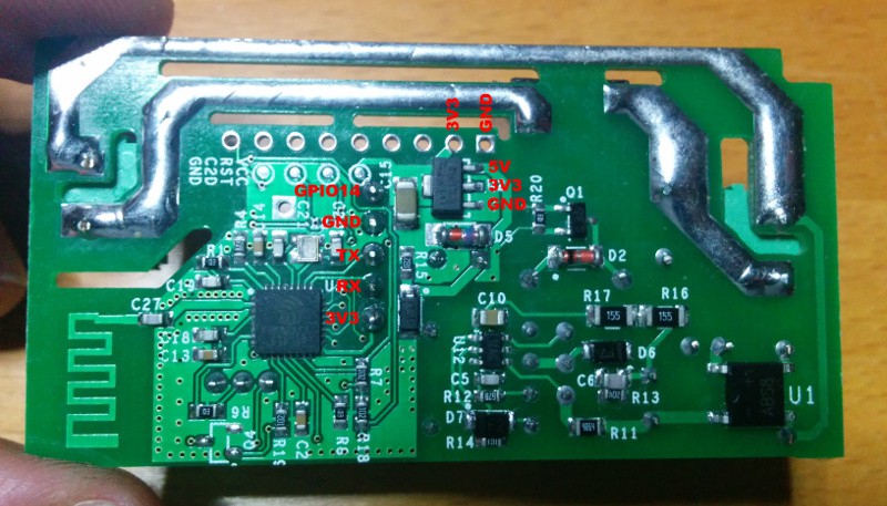
You need to access the serial interface. The four serial pins (3V3, Rx, Tx, GND) are available in the middle of the PCB, right next to the on-board button. Newer version of the Sonoff module provide five pins below the button, ignore the pin furthest away from the Button (GPIO14) if available. The square pin right next to the button is the 3.3V line.
For flashing the sonoff basic V1.1, please hold the button while connecting the Plus Pole. The LED remains off until the flashing process is done and the board is rebooted.
GPIO Locations


- GPIO 03 - RX PIN
- GPIO 01 - TX PIN
- GPIO 04 - Second image (must solder wire to pin on ESP chip)
- GPIO 14 - Below GND PIN