H801 - pauloromeira/Sonoff-Tasmota GitHub Wiki
It's not entirely clear where these devices come from originally, but they are available from AliExpress and eBay.
- AliExpress: https://www.aliexpress.com/wholesale?catId=0&SearchText=H801
- eBay: https://www.ebay.co.uk/sch/items/?_nkw=h801
Hardware
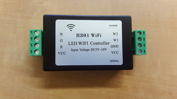
The chip used on this board is the ESP8266EX. 6 PWM outputs are connected to DTU35N06 MOSFETs to drive the 5 output channels (RGB + W1 + W2).
Serial Connection
Please see the Hardware Preparation page for general instructions.
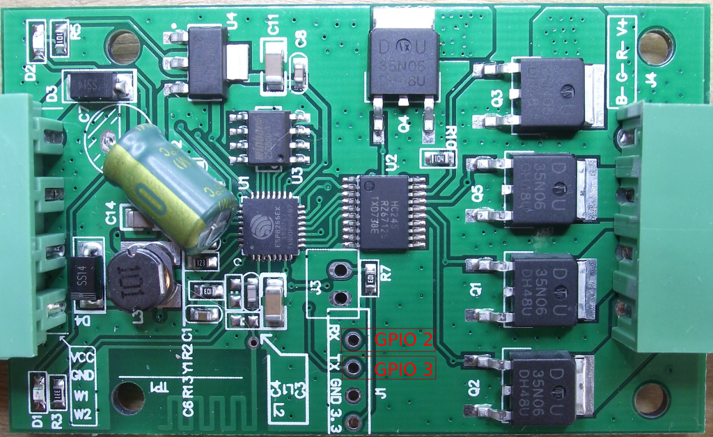
You need to access the serial interface. The unpopulated serial header (3V3, RX, TX, GND) are available in the middle of the PCB, right next to J3. Note: the RX and TX pins are labelled from the terminal's perspective, not from the perspective of the ESP chip. This means you should connect the RX and TX pins from your computer's UART to the RX and TX pins on the board respectively, not crossing them over!
To place the board into flashing mode, you will need to short J3. This can remain shorted while flashing is in progress, but you will need to remove the short in order to boot the Tasmota firmware.
First Boot
Most boards supported by the Tasmota firmware use GPIO 1 for serial TX. The H801, as shown in the image above, uses GPIO 2. As the serial RX is still the same as for other boards, it is possible for Tasmota to read from the serial connection but anything written will not be sent to your terminal. Blindly type the following command to set Tasmota to the H801 module type, and it will automatically switch to using GPIO 2 for serial TX allowing setup to proceed:
module 20
See #2155 for more details.