PDP 1 Handbook - parsa/simh GitHub Wiki
                           PROGRAMMED DATA
                             PROCESSOR-1
                              HANDBOOK

Copyright 1960, 1961, 1962, 1963 by Digital Equipment Corporation

     DIGITAL EQUIPMENT CORPORATION o MAYNARD, MASSACHUSETTS
- Programmed Data Processor 1
- PDP-1 Picture #1 from sunsite.unc.edu
- PDP-1 Picture #2 from sunsite.unc.edu
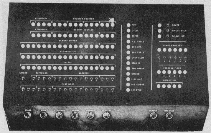
- PDP-1 Control Panel
- High Speed Perforated Tape Reader
- Perforated Tape Punch
- Alphanumeric Typewriter Keyboard
- Sequence Break Indicator Panel
- Precision CRT Display with Light Pen
- Precision CRT Display Type 30
- Ultra-Precision CRT
- Magnetic Tape Control and Transports
The Programmed Data Processor (PDP-1) is a high speed, solid state digital computer designed to operate with many types of input-output devices with no internal machine changes. It is a single address, single instruction, stored program computer with powerful program features. Five-megacycle circuits, a magnetic core memory and fully parallel processing make possible a computation rate of 100,000 additions per second. The PDP-1 is unusually versatile. It is easy to install, operate and maintain. Conventional 110-volt power is used, neither air conditioning nor floor reinforcement is necessary, and preventive maintenance is provided for by built-in marginal checking circuits.
PDP-1 circuits are based on the designs of DEC's highly successful and reliable System Modules. Flip-flops and most switches use saturating transistors. Primary active elements are Micro-Alloy-Diffused transistors.
The entire computer occupies only 17 square feet of floor space. It consists of four equipment frames, one of which is used as the operating station.
The Central Processor contains the control, arithmetic and memory addressing elements, and the memory buffer register. The word length is 18 binary digits. Instructions are performed in multiples of the memory cycle time of five microseconds. Add, subtract, deposit, and load, for example, are two-cycle instructions requiring 10 microseconds. Multiplication requires and average of 20 microseconds. Program features include: single address instructions, multiple step indirect addressing and logical arithmetic commands. Console features include: flip-flop indicators grouped for convenient octal reading, six program flags for automatic setting and computer sensing, and six sense switches for manual setting and computer sensing.
The coincident-current, magnetic core memory of a standard PDP-1 holds 4096 words of 18 bits each. Memory capacity may be readily expanded, in increments of 4096 words, to a maximum of 65,536 words. The read-rewrite time of the memory is five microseconds, the basic computer rate. Driving currents are automatically adjusted to compensate for temperature variations between 50 and 110 degrees Fahrenheit. The core memory storage may be supplemented by up to 24 magnetic tape transports.
PDP-1 is designed to operate a variety of buffered input-output devices. Standard equipment consistes of a perforated tape reader with a read speed of 400 lines per second, and alphanuermic typewriter for on-line operation in both input and output, and a perforated tape punch (alphanumeric or binary) with a speed of 63 lines per second. A variety of optional equipment is available, including the following:
- Precision CRT Display Type 30
- Ultra-Precision CRT Display Type 31
- Symbol Generator Type 33
- Light Pen Type 32
- Oscilloscope Display Type 34
- Card Punch Control Type 40-1
- Card Reader and Control Type 421
- Magnetic Tape Transport Type 50
- Programmed Magnetic Tape Control Type 51
- Automatic Magnetic Tape Control Type 52
- Automatic Magnetic Tape Control Type 510
- Parallel Drum Type 23
- Automatic Line Printer and Control Type 64
- 18-bit Real Time Clock
- 18-bit Output Relay Buffer Type 140
- Multiplexed A-D Converter Type 138/139
All in-out operations are performed through the In-Out Register or through the high speed input-output channels.
The PDP-1 is also available with the optional Sequence Break System. This is a multi-channel priority interrupt feature which permits concurrent operation of several in-out devices. A one-channel Sequence Break System is included in the standard PDP-1. Optional Sequence Break Systems consist of 16, 32, 64, 128, and 256 channels.
The Central Processor of PDP-1 contains the Control Element, the Memory Buffer Register, the Arithmetic Element, and the Memory Addressing Element. The Control Element governs the complete operation of the computer including memory timing, instruction performance and the initiation of input-output commands. The Arithmetic Element, which includes the Accumulator and the In-Out Register, performs the arithmetic operations. The Memory Addressing Element, which includes the Program Counter and the Memory Address Register, performs address bookkeeping and modification.
The powerful programming features of PDP-1 include:
- Multiple step indirect addressing
- Boolean operations
- Twelve variations of arithmetic and logical shifting, operating on 18 or 36 bits
- Fifteen basic conditional skip instructions (expandable by combining to form the inclusive OR of the separate conditions)
- Three different subroutine calling instructions
- Micro-coded operate instructions
- Index and Index-Conditional instructions
- Execute instruction
- Load-immediate instructions
- Built-in multiply and divide instructions
Six independent flip-flops, called program flags, are available for use as program switches or special in-out synchronizers. Multiply and divide operate in about 20 and 35 microseconds respectively.
The PDP-1 is a "fixed point" machine using binary arithmetic. Negative numbers are represented as the one's complement of the positive numbers. Bit 0 is the sign bit which is ZERO for positive numbers. Bits 1 to 17 are magnitude bits, with Bit 1 being the most significant and Bit 17 being the least significant. To avoid a frequent point of confusion in one's complement arithmetic, the representation of -0 is automatically changed to +0 in certain arithmetic operations.
The conversion of decimal numbers into the binary system for use by the machine is performed by subroutines. Similarly the output conversion of binary numbers into decimals is done by subroutine. Operations for floating point numbers are handled by interpretive programming.
The Bits 0 through 4 define the instruction code; thus there are 32 possible instruction codes, not all of which are used. The instructions may be divided into two classes:
- Memory Reference instructions
- Augmented instructions
In the memory reference instructions, Bit 5 is the indirect address bit. The instruction memory address, Y, is in Bits 6 through 17. These digits are sufficient to address 4096 words of memory.
The augmented instructions use Bits 5 through 17 to specify variations of the basic instruction. For example, in the shift instruction, Bit 5 specifies direction of shift, Bit 6 specifies the character of the shift (arithmetic or logical), Bits 7 and 8 enable the registers (01 = AC, 10 = IO, and 11 = both) and Bits 9 through 17 specify the number of steps.
A memory reference instruction which is to use an indirect address will have a ONE in Bit 5 of the instruction word. The original address, Y, of the instruction will not be used to locate the operand, jump location, etc., of the instruction, as in the normal case. Instead it is used to locate a memory register whose contents in Bits 6 through 17 will be used as the address of the original instruction. Thus, Y is not the location of the operand but the location of the location of the operand. If the memory register containing the indirect address also has a ONE in bit 5, the indirect addressing procedure is repeated and a third address is located. There is no limit to the number of times this process can be repeated.
Operating times of PDP-1 instructions are multiples of the memory cycle of 5 microseconds. Two-cycle instructions refer twice to memory and thus require 10 microseconds for completion. Examples of this are add, subtract, deposit, load, etc. The jump, augmented and combined augmented instructions need only one call on memory and are performed in 5 microseconds.
In-Out Transfer instructions that do not include the optional wait function require 5 microseconds. If the in-out device requires a wait time for completion, the operating time depends upon the device being used.
Each step of indirect addressing requires an additional 5 microseconds.
The Console of PDP-1 has controls and indicators for the use of the operator. All active registers have indicator lights on the Console. These indicators are primarily for use when the machine has stopped or when the machine is being operated one step at a time.
Three banks of toggle switches are available on the Console. These are the Address Switches (16 bits), the Test Word Switches (18 bits), and the Sense Switches (6 bits). The first two are primarily used in conjunction with the operating push buttons. The Sense Switches are present for manual intervention. The use of these switches is determnined by the program.
The first instruction executed comes from the memory location indicated by the Address and Extension Switches. If Start is pushed up, the computer enters the Sequence Break Mode before starting; if pushed down, the computer leaves the Sequence Break Mode. In either case, the overflow flip-flop is cleared and the Extend Switch condition is read into the Extend flip-flop.
The computer will come to a halt at the completion of the current memory cycle.
The computer will resume operation starting from the point where it was stopped.
The contents of the memory register indicated by the Address and Extension Switches will be displayed in the Accumulator and Memory Buffer lights.
The word in the Test Word Switches will be put in the memory location indicated by the Address and Extension Switches.
The Perforated Tape Reader will start operating in the Read-In mode.
When pushed up, turns Perforated Tape Reader motor on; when pushed down, turns it off.
When switch is pressed, Tape Punch feeds blank tape.
When Start or Read In is pressed, the state of this switch is read into the Extend flip-flop.
Specify which memory module will be used when Start, Examine, Deposit, or Read In are pressed.
Specify memory location for Start, Examine, and Deposit.
Specifies the word to be put in memory when Deposit is pressed. Can be read into the AC under program control.
Convenient switches whose conditions may be individually tested by the program.
On while the computer is executing instructions.
On after the completion of one or more instruction cycles with oneor more to follow.
On immediately prior to and during the execution of any deferred cycle.
On while the computer is executing a High Speed Channel Data Transfer.
On while the computer is executing cycle 1 (deposit Accumulator) and cycle 3 (deposit Input-Output Register) of a sequence break.
On while the computer is executing cycle 2 (deposit Program Counter) and cycle 3 of a sequence break.
On if overflow has occurred. (Can only be turned off or cleared by side} executing the Skip on Zero Overflow instruction or pressing Start.)
On while the computer is reading punched tape in the Read-In mode.
On while the computer is in the Sequence Break mode.
On while the computer is in the Extend mode.
On while the computer is executing an Input-Output Transfer wait.
On while in-out transfer instructions can be executed.
On for the time between device completion and end of In-Out wait.
On after the computer has executred the Set Selected Program Flag instruction or an in-out device has been activated, indicating its readiness to be serviced. (Can only be turned off or cleared by executing the Clear Selected Program Flag instruction.)
Displays 12 or 16 bits which represent the address of the next instruction to be executed.
Displays 5 bits which represent the basic operation code of the instruction being executed.
Displays 12 or 16 bits which represent the address of the instruction being executed (during cycle 0) or the address of the operand (in succeeding cycles)
Displays 18 bits which represent the instruction being executed (operation code and address part during cycle 0) or the 18-bit operand (in succeeding cycles)
Displays the 18 bits of the Accumulator which represent the results of arithmetic and logical operations.
Displays the 18 bits of the Input-Output Register which represent information just transferred in or out of the computer or the results of certain arithmetic and logical operations
This list includes the title of the instruction, the normal execution time of the instruction, (i.e., the time with no indirect address,) the mnemonic code of the instruction, and the operation code number. In the following list, the contents of a register are indicated by C(). Thus C(Y) means the contents of memory at Address Y; C(AC) means the contents of the Accumulator; C(IO) means the contents of the In-Out Register. An alphabetical and numerical listing of the instructions is contained on pages 62 to 67 (of the FrameMaker copy).
Add (10 µsec)
add Y Operation Code 40
The new C(AC) are the sum of C(Y) and the original C(AC). The C(Y) are unchanged. The addition is performed with 1's complement arithmetic. If the sum of two like-signed numbers yields a result of the opposite sign, the overflow flip-flop will be set (see Skip Group instructions). A result of minus zero is changed to plus zero.
Subtract (10 µsec)
sub Y Operation Code 42
The new C(AC) are the original C(AC) minus the C(Y). The C(Y) are unchanged. The subtraction is performed using 1's complement arithmetic. When two unlike-signed numbers are subtracted, the sign of the result must agree with the sign of the original Accumulator, or overflow flip-flop will be set (see Skip Group instructions). A result of minus zero can exist in one instance only: (-0) - (+0) = (-0)
Multiply (14 to 25 µsec)
mul Y Operation Code 54
The product of C(AC) and C(Y) is formed in the AC and IO registers. The sign of the product is in the AC sign bit. IO Bit 17 also contains the sign of the product. The magnitude of the product is the 34-bit string from AC Bit 1 throuh IO Bit 16. The C(Y) are not affected by this instruction. If the entire product results in a minus zero it is changed to a plus zero.
Divide (30 to 40 µsec, except on overflow, 12 µsec)
div Y Operation Code 56
The dividend must be in the AC and IO registers in the form indicated in the instruction, Multiply. IO bit 17 is ignored. The divisor is the C(Y). At the completion of the instruction, the C(AC) are the quotient and the C(IO) are the remainder. The sign of the remainder (in IO bit zero) is the sign of the dividend. The instruction that follows a DIV will be skipped unless an overflow occurs. The C(Y) are not affected by this instruction. If the remainder or quotient result is minus zero, that value is changed to plus zero.
If the magnitude of the high order part of the dividend is equal to or greater than the magnitude of the divisor, and overflow is indicated. In this case, the following instruction is not skipped. The original C(AC) and C(IO) are restored. The overflow flip-flop is not affected.
Index (10 µsec)
idx Y Operation Code 44
The C(Y) are replaced by C(Y) + 1 which are left in the Accumulator. The previous C(AC) are lost. Overflow is not indicated. If the original C(Y) equals the integer, -1, the result after indexing is plus zero.
Index and Skip if Positive (10 µsec)
isp Y Operation Code 46
The C(Y) are replaced by C(Y) + 1 which are left in the Accumulator. The previous C(AC) are lost. If, after the addition, the Accumulator is positive, the Program Counter is advanced one extra position and the next instruction in the sequence is skipped. Overflow is not indicated. If the original C(Y) equals the integer, -1, the result after indexing is plus zero and the skip takes place.
Logical AND (10 µsec)
and Y Operation Code 02
The bits of C(Y) operate on the corresponding bits of the Accumulator to form the logical AND. The result is left in the Accumulator. The C(Y) are unaffected by this instruction.
| AC Bit | Y Bit | Result |
|---|---|---|
| 0 | 0 | 0 |
| 0 | 1 | 0 |
| 1 | 0 | 0 |
| 1 | 1 | 1 |
Exclusive OR (10 µsec)
xor Y Operation Code 06
The bits of C(Y) operate on the corresponding bits of the Accumulator to form the exclusive OR. The result is left in the Accumulator. The C(Y) are unaffected by this order.
| AC Bit | Y Bit | Result |
|---|---|---|
| 0 | 0 | 0 |
| 0 | 1 | 1 |
| 1 | 0 | 1 |
| 1 | 1 | 0 |
Inclusive OR (10 µsec)
ior Y Operation Code 04
The bits of C(Y) operate on the corresponding bits of the Accumulator to form the inclusive OR. The result is left in the Accumulator. The C(Y) are unaffected by this order.
| AC Bit | Y Bit | Result |
|---|---|---|
| 0 | 0 | 0 |
| 0 | 1 | 1 |
| 1 | 0 | 1 |
| 1 | 1 | 1 |
Load Accumulator (10 µsec)
lac Y Operation Code 20
The C(Y) are placed in the Accumulator. The C(Y) are unchanged. The original C(AC) are lost
Deposit Accumulator (10 µsec)
dac Y Operation Code 24
The C(AC) replace the C(Y) in the memory. The C(AC) are left unchanged by this instruction. The C(Y) are lost.
Deposit Address Part (10 µsec)
dap Y Operation Code 26
Bits 6 through 17 of the Accumulator replace the corresponding digits of memory register Y. C(AC) are unchanged as are the contents of Bits 0 through 5 of Y. The original contents of Bits 6 through 17 of Y are lost.
Deposit Instruction Part (10 µsec)
dip Y Operation Code 30
Bits 0 through 5 of the Accumulator replace the corresponding digits of memory register Y. The Accumulator is unchanged as are bits 6 through 17 of Y. The original contents of Bits 0 through 5 of Y are lost.
Load In-Out Register (10 µsec)
lio Y Operation Code 22
The C(Y) are placed in the In-Out register. C(Y) are unchanged. The original C(IO) are lost.
Deposit In-Out Register (10 µsec)
dio Y Operation Code 32
The C(IO) replace the C(Y) in memory. The C(IO) are unaffected by this instruction. The original C(Y) are lost.
Deposit Zero in Memory (10 µsec)
dzm Y Operation Code 34
Clears (sets equal to plus zero) the contents of register Y.
Execute (5 µsec plus time of instruction executed)
xct Y Operation Code 10
The instruction located in register Y is executed. The Program Counter remains unchanged (unless a jump or skip were executed). If a skip instruction is executed (by xct y), the next instructions to be executed will be taken from the address of the xct y plus one or the the address of the xct y plus two depending on the skip condition. Execute may be indirectly addressed, and the instruction being executed may use indirect addressing. An xct instruction may execute other xct commands.
Jump (5 µsec)
jmp Y Operation Code 60
The next instruction executed will be taken from Memory Register Y. The Progra Counter is reset to Memory Address Y. The original contents of the Program Counter are lost.
Jump and Save Program Counter (5 µsec)
jsp Y Operation Code 62
The contents of the Program Counter are transferred to bits 6 through 17 of the AC. The state of the overflow flip-flop is transferred to bit zero, the condition of the Extend flip-flop to bit 1, and the contents of the Extended Program Counter to bits 2, 3, 4, and 5 of the AC. When the transfer takes place, the Program Counter holds the address of the instruction following the jsp. The Program Counter is then reset to Address Y. The next instruction executed will be taken from Memory Register Y. The original C(AC) are lost.
Call Subroutine (10 µsec)
cal Y Operation Code 16
The address part of the instruction, Y, is ignored. The contents of the AC are deposited in Memory Register 100. The contents of the Program Counter (holding the address of the instruction following the cal) are transferred to bits 6 through 17 of the AC. The state of the overflow flip-flop, the Extend flip-flop, and Extended Program Counter are saved as described under jsp. The next instruction executed is taken from Memory Register 101. The cal instruction requires that the indirect bit be zero. The instruction may be used as part of a master routine to call subroutines.
Jump and Deposit Accumulator (10 µsec)
jda Y Operation Code 17
The contents of the AC are deposited in Memory Register Y. The contents of the Program Counter (holding the address of the instruction following the jda) are transferred to bits 6 through 17 of the AC. The state of the overflow flip-flop, the Extend flip-flop, and Extended Program Counter are saved as described under jsp. The next instruction executed is taken from Memory Register Y + 1. The jda instruction requires that the indirect bit be a one, but indirect addressing does not occur. The instruction is equivalent to the instruction dac Y followed by jsp Y + 1. Skip if Accumulator and Y differ (10 usec) sad Y Operation Code 50 The C(Y) are compared with the C(AC). If the two numbers are different, the Program Counter is indexed one extra position and the next instruction in the sequence is skipped. The C(AC) and the C(Y) are unaffected by this operation.
Skip if Accumulator and Y are the same (10 µsec)
sas Y Operation Code 52
The C(Y) are compared with the C(AC). If the two numbers are identical, the Program Counter is indexed one extra position and the next instruction in the sequence is skipped. The C(AC) and the C(Y) are unaffected by this operation.
Load Accumulator with N (5 µsec)
law N Operation Code 70
The number in the memory address bits of the instruction word is placed in the Accumulator. If the indirect address bit is ONE, (-N) is put in the Accumulator.
Shift Group (5 µsec)
sft Operation Code 66
This group of instructions will rotate of shift the Accumulator and/or the In-Out Register. When the two registers operate combined, the In-Out Register is considered to be and 18-bit magnitude extension of the right end of the Accumulator.
Rotate is a non-arithmetic cyclic shift. That is the two ends of the register are logically tied together and information is rotated as though the reigster were a ring.
Shift is an arithmetic operation and is, in effect, multiplication of the number in the register by 2N, where N is the number of shifts; plus is left and minus is right. As bits are shifted out from one end of a register they are replaced at the other end by ones if the number negative and zeroes if the number is positive. The sign bit is not shifted.
The number of shift or rotate steps to be performed (N) is indicated by the number of ONE's in Bits 9 through 17 of the instruction word. Thus Rotate Accumulator Right nine times is 671777. A shift or rotate of one place can be indicated nine different ways. The usual convention is to use the right end of the instruction word (rar 1 = 671001).
When operating the PDP-1 in the single-step or single-instruction mode, shift group instructions may appear to operating incorrectly (i.e., judging from the indicator lights of the control console). This occurs because some shift group instructions overlap into the beginning of the next instruction.
Rotate Acumulator Right (5 µsec)
rar N Operation Code 671
Rotates the bits of the Accumulator right N positions, where N is the number of ONE's in Bits 9-17 of the instruction word.
Rotate Acumulator Left (5 µsec)
ral N Operation Code 661
Rotates the bits of the Accumulator left N positions, where N is the number of ONE's in Bits 9-17 of the instruction word.
Shift Acumulator Right (5 µsec)
sar N Operation Code 675
Shifts the contents of the Accumulator Right N positions, where N is the number of ONE's in Bits 9-17 of the instruction word.
Shift Acumulator Left (5 µsec)
sal N Operation Code 665
Shifts the contents of the Accumulator left N positions, where N is the number of ONE's in Bits 9-17 of the instruction word.
Rotate In-Out Register Right (5 µsec)
rir N Operation Code 672
Rotates the bits of the In-Out Register right N positions, where N is the number of ONE's in Bits 9-17 of the instruction word.
Rotate In-Out Register Left (5 µsec)
ril N Operation Code 662
Rotates the bits of the In-Out Register left N positions, where N is the number of ONE's in Bits 9-17 of the instruction word.
Shift In-Out Register Right (5 µsec)
sir N Operation Code 676
Shifts the contents of the In-Out Register right N positions, where N is the number of ONE's in Bits 9-17 of the instruction word.
Shift In-Out Register Left (5 µsec)
sil N Operation Code 666
Shifts the contents of the In-Out Register left N positions, where N is the number of ONE's in Bits 9-17 of the instruction word.
Rotate AC and IO Right (5 µsec)
rcr N Operation Code 673
Rotates the bits of the combined registers right in a single ring N positions, where N is the number of ONE's in Bits 9-17 of the instruction word.
Rotate AC and IO Left (5 µsec)
rcl N Operation Code 663
Rotates the bits of the combined registers left in a single ring N positions, where N is the number of ONE's in Bits 9-17 of the instruction word.
Shift AC and IO Right (5 µsec)
scr N Operation Code 677
Shifts the contents of the combined registers right N positions, where N is the number of ONE's in Bits 9-17 of the instruction word.
Shift AC and IO Left (5 µsec)
scl N Operation Code 667
Shifts the contents of the combined registers left N positions, where N is the number of ONE's in Bits 9-17 of the instruction word.
Skip Group (5 µsec)
skp Operation Code 64
This group of instructions senses the state of various flip-flops and switches in the machine. The address portion of the instruction selects the particular function to be sensed. All members of this group have the same operation code. The instructions in the Skip Group may be combined to form the inclusive OR of the separate skips. Thus, if Address 3000 is selected, the skip would occur if the overflow flip-flop equals ZERO or if the In-Out Register is positive.
The combined instruction would still take 5 microseconds.
The intent of any skip instruction can be reversed by making Bit 5 (normally the Indirect Address Bit) equal to One. For example, the Skip on Zero Accumulator instruction, with Bit euqal to one, becomes Do Not Skip on Zero Accumulator.
Skip on ZERO Accumulator (5 µsec)
sza Address 0100
If the Accumulator is equal to plus ZERO (all bits are ZERO), the Program Counter is advanced one extra position and the next instruction in the sequence is skipped.
Skip on Plus Accumulator (5 µsec)
spa Address 0200
If the sign bit of the Accumulator is ZERO, the Program Counter is advanced one extra position and the next instruction in the sequence is skipped.
Skip on Minus Accumulator (5 µsec)
sma Address 0400
If the sign bit of the Accumulator is ONE, the Program Counter is advanced one extra position and the next instruction in the sequence is skipped.
Skip on ZERO Overflow (5 µsec)
szo Address 1000
If the overflow flip-flop is a ZERO, the Program Counter is advanced one extra position and the next instruction in the sequence is skipped. The overflow flip-flop is cleared by the instruction. This flip-flop is set only by an addition or subtraction that exceeds the capacity of the Accumulator. (See definition of add and subtract instructions). The overflow flip-flop is not cleared by arithmetic operations which do not cause an overflow. Thus, a whole series of arithmetic operations can be checked for correctness by a single szo. The overflow flip-flop is cleared by the "Start" Switch.
Skip on Plus In-Out Register (5 µsec)
spi Address 2000
If the sign digit of the In-Out Register is ZERO, the Program Counter is indexed one extra position and the next instruction in the sequence is skipped.
Skip on Plus ZERO Switch (5 µsec)
szs Addresses 0010, 0020, ... 0070
If the selected Sense Switch is ZERO, the Program Counter is advanced one extra position and the next instruction in the sequence is skipped. Address 10 senses the position of Sense Switch 1, Address 20 Switch 2, etc. Address 70 senses all the switches If 70 is selected all 6 switches must be ZERO to cause the skip.
Operate Group (5 µsec)
opr Operation Code 76
This instruction group performs miscellaneous operations on various Central Processor Registers. The address portion of the instruction specifies the action to be performed.
The instructions in the Operate Group can be combined to give the union of the functions. The instruction opr 3200 will clear the AC, put TW to AC, and complement AC.
Clear In-Out Register (5 µsec)
cli Addres 4000
Clears (sets equal to plus zero) the In-Out Register.
Load Accumulator from Test Word (5 µsec)
lat Address 2000
Forms the inclusive OR of the C(AC) and the contents of the Test Word. This instruction is usually combined with Address 0200 (Clear Accumulator), so that C(AC) wil equal the contents of the Test Word Switches.
Load Accumulator with Program Counter (5 µsec)
lap Address 0100
Forms the inclusive OR of the C(AC) and the contents of the Program Counter (which contains the address of the instruction following the lap) in AC bits 6 through 17. Also, the inclusive OR of AC bit zero and the state of the overflow flip-flop is formed in AC bit zero. This instruction is usually combined with address 0200 (clear accumulator) so that the C(AC) will equal the contents of the overflow flip-flop (in AC bit zero) and the contents of the Program Counter (in AC bits 6 through 17). The contents of the Extend flip-flop are transferred to AC bit 1, the contents of the Extended Program Counter to bits 2, 3, 4, and 5.
Complement Accumulator (5 µsec)
cma Address 1000
Complements (changes all ones to zeroes and all zeroes to ones) the contents of the Accumulator.
Halt
hlt Address 0400
Stops the computer. Clear Accumulator (5 usec) cla Address 0200 Clears (sets equal to plus zero) the contents of the Accumulator.
Clear Selected Program Flag (5 µsec)
clf Address 0001 to 0007
Clears the selected program flag. Address 01 clears Program Flag 1, 02 clears Program Flag 2, etc. Address 07 clears all program flags.
Set Selected Program Flag (5 µsec)
stf Address 0011 to 0017
Sets the selected program flag. Address 11 sets Program Flag 1; 12 sets Program Flag 2, etc. Address 17 sets all program flags.
No Operation (5 µsec)
nop Address 0000
The state of the computer is unaffected by this operation, and the Program Counter continues in sequence.
In-Out Transfer Group (5 µsec without in-out wait
iot Operation Code 72
The variations within this group of instructions perform all the in-out control and information transfer functions. If Bit 5 (normally the Indirect Address bit) is a ONE, the computer will enter a special waiting state until the completion pulse from the activated device has returned. When this device delivers its completion, the computer will resume operation of the instruction sequence.
The computer may be interrupted from the special waiting state to serve a sequence break request or a high speed channel request.
Most in-out operations require a known minimum time before completion. This time may be utilized for programming. The appropriate In-Out Transfer can be given with no in-out wait (Bit 5 a ZERO and Bit 6 a ONE). The instruction sequence then continues. This sequence must include an iot instruction 730000 which performs nothing but the in-out wait. The computer will then enter the special waiting state until the device returns the in-out restart pulse. If the device has already returned the completion pulse before the instruction 730000, the computer will proceed immediately.
Bit 6 determines whether a completion pulse will or will not be received from the in-out device. When it is different than Bit 5, a completion pulse will be received. When it is the same as Bit 5, a completion pulse will not be received.
In addition to the control function of Bits 5 and 6, Bits 7 through 11 are also used as control bits serving to extend greatly the power of the iot instructions. For example, Bits 12 through 17, which are used to designate a class of input or output devices such as typewriters, may be further defined by Bits 7 through 11 as referring to Typewriter 1, 2, 3, etc. In several of the optional in-out devices, in particular the magnetic tape, Bits 7 through 11 specify particular functions such as forward, backward etc. If a large number of specialized devices are to be attached, these bits may be used to further the in-out transfer instruction to perform totally distinct functions.
The Perforated Tape Reader of the PDP-1 is a photoelectric device capable of reading 400 lines per second. Three lines form the standard 18-bit word when reading binary punched 8-hole tape. Five, six and seven hole tape may also be read.
Read Perforated Tape, Alphanumeric
rpa Address 0001
This instruction reads one line of tape (all eight Channels) and transfers the resulting 8-bit code to the Reader Buffer. If bits 5 and 6 of the rpa function are both zero (720001), the contents of the Reader Buffer must be transferred to the IO Register by executing the rrb instruction. When the Reader Buffer has information ready to be transferred to the IO Register, Status Register Bit 1 is set to one. If bits 5 and 6 are different (730001 or 724001) the 8-bit code read from tape is automatically transferred to the IO Register via the Reader Buffer and appears as follows:
IO Bits        10 11 12 13 14 15 16 17
TAPE CHANNELS  8  7  6  5  4  3  2  1
The remaining bits of the IO Register are set to zero.
The code of the off-line tape preparation typewriter (Friden FIO-DEC Recorder-Reproducer) contains an odd parity bit. This bit may be checked by the read-in program. The FIO-DEC Code can then be converted to the Concise (6-bit) Code used by PDP-1 merely by dropping the eighth bit (parity).
A list of characters and their FIO-DEC and Concise Codes can be found on pages 68 and 69 (of the FrameMaker copy).
Read Perforated Tape, Binary rpb
Address 0002
The instruction reads three lines of tape (six Channels per line) and assembles the resulting 18-bit word in the Reader Buffer. For a line to be recognized by this instruction Channel 8 must be punched (lines with Channel 8 not punched will be skipped over). Channel 7 is ignored. The instruction sub 5137, for example, appears on tape and is assembled by rpb as follows:
Channel 8 7 6 5 4 | 3 2 1
Line 1  X   X     |   X
Line 2  X   X   X |     X
Line 3  X     X X | X X X
Reader Buffer 100 010 101 001 011 111
(Vertical dashed line indicates sprocket holes and the symbols "X" indicate holes punched in tape).
If bits 5 and 6 of the rpb instruction are both zero (720002), the contents of the Reader Buffer must be transferred to the IO Register by executing a rrb instruction. When the Reader Buffer has information ready to be transfer red to the IO Register, Status Register Bit 1 is set to one. If bits 5 and 6 are different (730002 or 724002) the 18-bit word read from tape is automatically transferred to the IO Register via the Reader Buffer.
Read Reader Buffer
rrb Address 0030
When the rpa or rpb instructions are given with bits 5 and 6 both zero (720001 or 720002) information read from tape fills the Reader Buffer, but is not automatically transferred to the IO Register. To accomplish the transfer, these instructions must be followed by a rrb instruction. In addition, the rrb instruction clears Status Register Bit 1.
Read-In Mode
This is a special mode activated by the "Read-In" switch on the console. It provides a means of entering programs which does not rely on programs already in memory. Pushing the "Read-In" switch starts the reader in the binary mode. The first group of three lines, and alternate succeeding groups of three lines, are interpreted as "Read-In" mode instructions. Even-numbered groups o three lines are data. The "Read-In" mode instructions must be either "deposit in-out" (dio Y) or "jump" (jmp Y). If the instruction is dio Y, the next group of three binary lines will be stored in memory location Y and the reader continues moving. If the instruction is jmp Y, the "Read-In" mode is terminated, and the computer will commence operation at the address of the jump instruction.
The standard PDP-1 Perforated Tape Punch operates at a speed of 63 lines per second. It can operate in either the alphanumeric mode or the binary mode.
Punch Perforated Tape, Alphanumeric
ppa Address 0005
For each In-Out Transfer instruction one line of tape is punched. In-Out Register Bit 17 conditions Hole 1. Bit 16 conditions Hole 2, etc. Bit 10 conditions Hole 8.
Punch Perforated Tape, Binary
ppb Addres 0006
For each In-Out Transfer instruction one line of tape is punched. In-Out Register Bit 5 conditions Hole 1. Bit 4 conditions Hole 2, etc. Bit 0 conditions Hole 6. Hole 7 is left blank. Hole 8 is always punched in this mode.
The typewriter will operate in the input mode or the output mode.
Type Out
tyo Address 0003
For each In-Out Transfer instruction one character is typed. The character is specified by the right six bits of the In-Out Register.
Type In
tyi Address 0004
This operation is completely asynchronous and is therefore handled differently than any of the preceding in-out operations.
When a typewriter key is struck, the code for the struck key is placed in the typewriter buffer, Program Flag 1 is set, and the type-in status bit is set to one. A program designed to accept typed-in data would periodically check Program Flag 1, and if found to be set, an In-Out Transfer Instruction with address 4 could be executed for the information to be transferred to the In-Out Register. This In-Out Transfer should not use the optional in-out wait. The information contained in the typewriter buffer is then transferred to the right six bits of the In-Out Register. The tyi instruction automatically clears the In-Out Register before transferring the information and also clears the type-in status bit.
The purpose of the Sequence Break Mode (or program interrupt) is to allow concurrent operation of several in-out devices and the main program sequence. It also provides a means of indicating to the computer that an in-out device is ready to accept or furnish data.
Interrupt requests can be received from any number of in-out devices. Each such request sets a unique status bit. If the channel is free, the main program sequence is interrupted after completion of the current memory cycle and the C(AC) are automatically stored in memory location zero, the C(PC) in location 1, and the C(IO) in location 2. The time required to accomplish this is 15 _u_sec. The C(PC) as stored in location includes the state of the overflow flip-flop in bit zero. The Program Counter is then reset to the address 0003 and the program begins operating in the new sequence. The program beginning at location 0003 is usually designed to inspect the status bits, through the use of the Check Status instruction, to determine which in-out device caused the interrupt. A jump to the appropriate in-out subroutine can then be executed. Each such subroutine is terminated by the following instructions:
lac              0000 (to restore the AC)
lio              0002 (to restore the IO)
jmp (indirect)   0001 (to resume the main program)
The last of these three instructions restores the overflow and PC flip-flops and frees the channel thus allowing the next interrupt request received by the system to be processed. Interrupt requests that occurred while the channel was busy set status bits, and cause interrupts when the channel next becomes free.
In the standard PDP-1 the reader, punch, and typewriter are attached to the One-Channel Sequence Break System and five status bits are defined (see Check Status instruction). The number of status bits is expanded as required by optional in-out equipment.
Three instructions are directly associated wih the One-Channel Sequence Break System on the standard PDP-1:
Enter Sequence Break Mode
esm Address 0055
This instruction turns on the Sequence Break System, allowing automatic interrupts to the main sequence to occur.
Leave Sequence Break Mode
lsm Address 0054
This instruction turns off the Sequence Break System, thus preventing interrupts to the main sequence. Should interrupt requests occur while the system is off, the status bits will, nevertheless continue to be set.
Clear Sequence Break System
cbs Address 0056
This instruction clears certain control flip-flops in the Sequence Break System thus nullifying the effect of any interrupt requests just granted or about to be granted (i.e., just prior to the transfer of the C(AC) to location zero).
Check Status
cks Address 0033
This instruction checks the status of various in-out devices and sets IO Bits 0 through 6 for subsequent program interrogation as follows:
| IO Bit Positions | Status Register Definitions |
|---|---|
| 0 |
|
| 1 |
|
| 2 |
|
| 3 |
|
| 4 |
|
| 5 |
|
| 6 |
|
In order to maintain compatibility with older programs, and in cases where the maximum automatic multiply and divide times are not allowable, switches are provided to select programmed multiply and divide, using the following instructions:
Multiply Step (10 µsec)
mus Y Operation Code 54
Bit 17 of the In-Out Register is a ONE, the C(Y) are added to C(AC). If IO Bit 17 is a ZERO, the addition does not take place. In either case, the C(AC) and C(IO) are rotated right one place. AC Bit 0 is made ZERO by this rotate. This instruction is used in the multiply subroutine.
Divide Step (10 µsec)
dis Y Operation Code 56
The Accumulator and the In-Out Register are rotated left one place. IO Bit 17 receives the complement of AC Bit 0. If IO Bit 17 is ONE, the C(Y) are subtraced from C(AC).
If IO Bit 17 is ZERO, C(Y) + 1 are added to C(AC). This instruction is used in the divide subroutine A result of minus zero is changed to plus zero.
Each Memory Module consists of 4096, 18-bit words. A maximum of sixteen such modules may be connected to the PDP-1 thus allowing for a maximum memory capacity of 65536 words.
This control allows for memory expansion beyond 4096 to a maximum of 65536 18-bit words in increments of 4096-word modules. It provides a single-level, indirect address mode called "extend", in addition to the normal multiple-level, indirect address mode of the standard PDP-1. A toggle switch labelled "extend", which is on the control console, provides for initial selection of the extend or normal mode in conjunction with the use of the Start of Read-In Push-Buttons. During the operation of the program, the extend or normal mode can be selected as required through the use of two instructions provided with this options:
Enter Extend Mode (5 µsec)
eem 724074
This instruction places the computer in the single-level, indirect address mode called "extend". In this mode, all memory reference instructions that are indirectly addressed refer to the location of a word which is taken as a 16-bit effective address. This address is contained in bits 2 through 17 of the specified word. The Program Counter (PC) and the Memory Address Register (MA) both become 16-bit registers. When a jsp, jda, cal, or lap (with address 300) instruction is executed, the AC receives the state of the overflow flip-flop in bit zero, the state of the indirect address mode (extend = 1, normal = 0) in bit 1, and the contents of the extended Program Counter in bits 2 through 17. Instructions not indirectly addressed are executed as in the standard PDP-1, but refer to the 4096 words in the memory module designated by the program counter extension, PC bits 2 through 5. Only bits 6 through 17 of the extended Program Counter act as a counter. Therefore, unless a transfer of control is indicated, an instruction in location 7777 is followed by the instruction in location 0000 of the same memory module, as specified by PC bits 2 through 5. In the extend mode, the cal instruction used memory locations 0100 and 0101 in memory module designated by the extended Program Counter, PC bits 2 through 5.
Leave Extend Mode (5 µsec)
lem 720074
This instruction places the computer in the multiple-level, indirect address mode called "normal". In this mode, the PDP-1 operates as usual and all addresing refers to the 4096 words in the memory module designated by the program counter extension, PC bits 2 through 5. As in the extend mode, the instructions jsp, jda, cal, and lap (with address 300) supply the AC with the contents of the overflow, indirect address mode, and PC flip-flops. In the normal mode, the cal instruction uses memory locations 0100 and 0101 in the memory module designated by the program counter extension, PC bits 2 through 5.
High Speed Channel transfers performed with extended memory refer directly to any of 65536 memory locations, regardless of the state of the indirect address mode (extend or normal).
Sequence break operations with extended memory use Memory Module zero, locations 00 through 03 (one-channel system) or 00 through 77 (sixteen-channel system) to store the C(AC), C(PC), and C(IO) and to jump to the new sequence. The C(PC) as stored in the second fixed location assigned to each channel includes the state of the overflow flip-flop in bit zero, the state of the indirect address mode (extend = 1, normal = 0) in bit 1, and the contents of the extended Program Counter in bits 2 through 17. At the beginning of a sequence break the overflow and indirect addres mode flip-flops are automatically set to zero. The indirect jump that terminates a sequence break requires the Sequence Break System to be on, temporarily places the computer in the extend mode, then restores the overflow, indirect address mode, and PC flip-flops to their previous stages (i.e., just prior to the beginning of the sequence break).
This control is used in conjunction with the High Speed Data Control (Type 131). A maximum of three such channels can be attached to the PDP-1 through this control. Automatic Magnetic Tape Control Type 52 includes the installation of a Type 19 control. A high speed channel is used to automatically transfer blocks of words between core memory and an in-out device. Each channel is automatically interrogated at the completion of each memory cycle on a priority basis. The priority is wired and fixed. The Sequence Break System has an overall priority just below that of the lowest priority high speed channel. When wired to this channel, a device communicates directly with memory through the Memory Buffer Register, by passing the IO Register. After proper initiation, data transfers proceed without disturbing the main program. If the channel has a word for or needs a word from the memory, the current program sequence pauses for on memory cycle (5 _u_sec) to serve that channel, then continues. The maximum rate of transfer is 200,000 (18-bit) words per second.
The purpose of the Sequence Break System (or program interrupt system) is to allow concurrent operation of several in-out devices and the main program sequence. This system has, nominally, sixteen automatic interrupt channels arranged in a priority chain. Four fixed and unique memory locations are assigned to each sequence break channel. Channel zero (highest priority) uses locations 0, 1, 2, and 3; channel one uses locations 4, 5, 6, and 7; etc. A break to a particular sequence can be initiated by the completion of an in-out device, the program or any external signal. If this sequence has priority, the C(AC) are automatically stored in the first of four assigned memory location, the C(PC) in the second,. and the C(IO) in the third. The time required to accomplish this is 15 microseconds (during which other interrupts cannot occur). The C(PC) as stored in the second location includes the state of the overflow flip-flop in bit zero. The Program Counter is reset to the addres of the fourth fixed location and the program begins operating in the new sequence. This new sequence may be broken by a higher priority sequence. A typical program for handling an in-out sequence would contain several instructions, including the appropriate IOT instruction. These are followed by load AC and load IO from their fixed locations and an indirect jump to the location of the previous C(PC). This last instruction also restores the previous state of the overflow flip-flop and terminates the sequence.
When the Type 120 Sequence Break System is installed in the PDP-1, the standard one-channel system is removed. The three instructions asociated with the one-channel system are retained and four additional instructions are provided:
Deactivate Sequence Break Channel
dsc 72kn50
Turn off the channel specified by kn, where kn equals 00 for channel zero, 01 for channel one, etc., and 17 for channel fifteen.
Activate Sequence Break Channel
asc 72kn51
Turn on the channel specified by kn.
Initiate Sequence Break
isb 72kn52
Initiate a sequence break on the channel specified by kn regardless of whether the channel is on or off.
Clear All Channels
cac 720053
Turns off all sixteen channels.
Sequence Break Systems with 32, 64, 128, and 256 channels are also available and operate in the same manner.
The High Speed Data Control Type 131 automatically transfers data between the PDP-1 and an input-output device. After proper inititialization, data-transfers to and from the Data Control proceed concurrently with the main computer program. The maximum transfer rate is 200,000 18-bit words per second, based on the 5 _u_sec computer memory cycle.
A maximum of three Data Controls can be attached to a Type 19 High Speed Channel Control of the PDP-1. Each Data Control is asigned a priority to halt the program for data transfers with core memory. Each Data Control can operate three devices, one at a time. The Type 131 contains five major registers:
ONE BUFFER (1 Buf)
An 18-bit register acting as an intermediate storage buffer for Memory Buffer Register information received from the High Speed Channel Control or an external device. During incoming transfers it is an intermediate buffer between the Data Word Buffer (DWB) of the external device and the Two Buffer.
TWO BUFFER (2 Buf)
An 18-bit registed tha holds outgoing information to be transferred into the DWB of an external device or into the Memory Buffer Register of the computer during a high speed channel transfer.
DEVICE REGISTER (D Reg)
A 3-bit static register used to control the flow of information and connect the desired external device. The register is loaded from the Memory Buffer Register buss.
INITIAL LOCATION COUNTER (ILC)
A 16-bit register that contains the address of the next data word to be transferred and is advanced one each time a data word is transferred. This register is loaded from the IO Register.
WORD COUNTER (WC)
A 16-bit register containing the complement of the number of words remaining to be transferred in the data block. The counter is ad- vanced one each time a word is transferred to an external device DWB. Note that the Word Counter outputs are decoded and combined with logic levels to stop all further high speed channel requests at the proper time. This register is loaded from the IO Register.
The IOT instruction structure for the Type 131 Data Control is 72xxyy, where
- 72 specifies IOT
- xx microprogramming
- yy Data Control selection
Set Word Counter
swc Address x046
Transfers the contents of the IO Register into the Word Counter in the Data Control. the contents of the IO Register at this time should contain the address specifications concerning the number of computer words to be transferred via the High Speed Channel Control Type 19. In addition, Memory Buffer Register bits 6 through 8 are transferred to the Device Register. These bits should specify he direction of data transfer and the device to be connected to the Data Control.
| MB Bit | State | Description |
|---|---|---|
| 6 | 0 | Data is to be transferred into the computer |
| 6 | 1 | Data is to transferred out from the computer |
| 7 and 8 | 00 | No device connected |
| 7 and 8 | 10 | Connect Tape Control, Type 510 |
| 7 and 8 | 01 | Connect device 2 |
| 7 and 8 | 11 | Connect device 3 |
Set Initial Address
sia Address 0346
Transfers the contents of the IO Register into the Initial Location Counter in the Data Control. The contents at this time should be the address specifications concerning the location of the initial computer data word to be transferred from or put into core memory.
Stop Data Flow
sdf Address 0146
Disconnects all devices from the Data Control.
Read Location Counter
rlc Address 0366
Transfers the contents of Initial Location Counter to the IO Register of the computer. This instrucion can be executed twice to compare the results before accepting the location as a check of synchronism. The asynchronous nature of this instruction makes it useful to examine the contents of the Initial Location Counter at any time. In addition, this instruction transfers two status bits into the IO Register.
| IO Bit | State | Description |
|---|---|---|
| 0 | 0 | Transfer in progress |
| 0 | 1 | Word counter equals zero; transfers complete |
| 1 | 0 | Data Transfer is on time |
| 1 | 1 | Data transfer is later. This signifies that the computer did not take the data in and new data was transferred in over old in the Data Control buffers. |
NOTE: The data late condition can exist with the Tape Control on the third priority high speed channel if simultaneous request on all channels is preceeded by multiply or divide, when operating the Tape Control at a density of 800 cpi.
Set High Speed Channel Request
shr Address 0446
Forces a high speed channel cycle request to transfer data.
In the sequence break mode of operation the Word Count Equal to Zero (WC = 0) output signal of the Data Control is assigned to a particular channel on the Type 120 Sequence Break System. Therefore, programming to synchronize on the completion of the issued transfer instruction varies according to the channel assignment. To synchronize on the completion of the transfer with the standard Single Channel Sequence Break System the WC = 0 signal is sent to bit 8 of the computer Status Register.
Synchronization for transfer completion can be accomplished out of the sequence break mode by use of the rlc instruction. In this manner, WC = 0 when a ZERO is transferred to bit 0 of the IO Register.
This sixteen-inch cathode ray tube display is intended to be used as an on-line output device for the PDP-1. It is useful for high speed presentation of graphs, diagrams, drawings, and alphanumerical information. The unit is solid state, self-powered and completely buffered. It has magnetic focus and deflection.
Display characteristics are as follows:
- Random point plotting
- Accuracy of points +/-3 per cent of raster size
- Raster size 9.25 by 9.25 inches
- 1024 by 1024 addressable locations
- Fixed origin at center of CRT
- Ones complement binary arithmetic
- Plots 20,000 points per second
Resolution is such that 512 points along each axis are discernable on the face of the tube.
One instruction is added to the PDP-1 with the installation of this display:
Display One Point On CRT
dpy Address 0007
This instruction clears the light pen status bit and displays one point using bits 0 through 9 of the AC to represent the (signed) X coordinate of the point and bits 0 through 9 of the IO as the (signed) Y coordinate.
Many variations of the Type 30 Display are available. Some of these include hardware for line and curve generation.
The Type 33 Symbol Generator automatically translates digital computer words into format information for rapid display on a Type 30 CRT. The Type 33 plots symbols on a 5 x 7, 35-dot matrix in one of four sizes. Individual symbols are displayed by intensifying spots within the matrix under program control. Character and symbol information is received from the computer in the form of two 18-bit words.
The Type 33 greatly increases the Type 30's capacity for character and symbol generation. Plotting rate is increased approximately ten times: a total of 220 characters (based on an average character of 16 points) can be displayed flicker free. Any symbol compatible with a 5 x 7, 35-dot matrix can be displayed. The Type 33 includes a subscript control with adjustable offset and an increment control which spaces successive symbols one position to the right.
Generator Plot Left
gpl Address 2027
Transfers the contents of the IO Register to the shift register of the Symbol Generator and initiates plotting of the first 17 dots. Bit 17 of this word sets or resets the subscript control if the bit is a one or a zero, respectively.
Generator Plot Right
gpr Address 0027
Transfers the contents of the IO register to the shift register of the symbol generator and initiates plotting of the last 18 dots. The "Clear" is inhibited by MD bit 7 = 0 to prevent losing the count contained in the horizontal and vertical counters which control dot position.
Reset
gcf Address 0127
Clears the light pen status flip-flop in the display. The light pen status will also be cleared when a normal point plot (iot 07) is performed.
Load Format
glf Address 2026
Reads the three least significant bits of the IO Register to the two character-size control flip-flops .Bits 16 and 17 are used to specify one of the four symbol sizes. Bit 15, if a 1, specifies automatic spacing between symbols. A completion pulse will not be generated by the display when this instruction is performed.
Space
jsp Address 0026
Increments the X buffer-counter to position the beam one character position to the right. Since the contents of the IO Register are transferred to the Shift Register by this instruction, the IO Register should be cleared before performing the jsp instruction. The Increment control must be set before performing the jsp instruction by loading bit 15 with the glf instruction.
Intensify
dpy Address 0007

No Intensify
sdb Address 2007
By use of the MB bit 12, the normal point plotting instruction dpy can be used to load the position co-ordinates of the first character to be displayed without illuminating that point. When the "No Intensify" instruction is performed the display will not generate a completion pulse, therefore the programmer must allow at least 25 usec before executing a gpl instruction.
Except for the gcf, glf and sdb instructions, which do not cause the generation of a completion pulse, the preceding iot instructions can be coded to perform the in-out wait operations.
The Light Pen is designed to be used with the CRT Display Type 30. By "writing" on the face of the CRT, stored or displayed information can be expanded, deleted or modified. Specifically, each time a light-pulse strikes the pen, the Light Pen status bit is set to one (see definition of Check Status Instruction) and Program Flag 3 is set to one. At the time the status bit is set, the x-y coordinates of the point just "seen" by the pen are in bits 0 through 9 of the AC and bits 0 through 9 of the IO, repsectively (if the Display Instruction was given the optional in-out wait). A program designed to accept Light Pen input would periodically check the Light Pen status bit and when found to be set, would store the C(AC) and the C(IO) thereby defining the point just "seen" by the pen.
The operation of this high resolution, five-inch cathode ray tube display is similar to that of the Type 30. Its resolution, accuracy, and stability, however, are such that it is much more suitable for the accurate, photographic recording of data. The specifications differ as follows:
- Raster Size 3 by 3 inches
- Accuracy of points is +/- 1/2 percent of raster size
- 4096 by 4096 addressable locations
Resolution is such that 1024 points along each axis are discernable on the face of the tube.
One instruction is added to the PDP-1 with the installation of this display:
Display One Point on Precision CRT
dpp Address 0407
This instruction displays one point using bits 0 through 11 of the AC to represent the (signed) X coordinate of the point and bits 0 through 11 of the IO as the (signed) Y coordinate.
This control allows for on-line, buffered operation of standard card punch equipment. It contains an 80-bit buffer, loaded from the IO Register using one iot five times for each card row punched. Since any or all punching positions may be used, the standard IBM format is not a restriction and any format may be used. Maximum speed of the punch is 100 cards per minute. The instructions for the Type 40-1 are:
Load a Group
lag Address 0044
Loads 18 bits into the Control buffer. Five lag instructions are required to load the 80-bit buffer.
Punch a Card
pac address 0043
Starts the punching operation.
The Type 41 provides on-line reading of standard punched cards. Cards are read lengthwise and sensed optically. They may be read in the alphanumeric or binary mode at rates of up to 200 cards per minute. Output is 6 parallel bits.
The alphanumeric mode converts the 12-bit Hollerith code of one column into the 6-bit binary-coded decimal code with code validity checking. The binary mode reads a 12-bit column directly into the computer. Hopper and stacker capacity is 500 cards.
The instructions for the Type 421 Card Reader are:
Read Card Alpha
rac Address 0041
Select a card in alphanumeric mode. Select the card reader and start a card moving. Information will appear in alphanumeric form.
Read Card Binary
rbc Address 0042
Select a card in binary mode. Select the card reader and start a card moving Information will appear in binary form.
Read Column Register
rcc Address 0032
Read the card column buffer information into the IO Register and the clear the Card Reader flag. One rcc reads alphanumeric information Two rcc instructions read the upper and lower column binary information.
This transport is compatible with IBM tape formats with a recording density of 200 7-bit characters per inch, an inter-record gap of 3/4 inches, and an interfile gap of 3-1/2 inches. The read-write speed of 75 inches per second provides for a 15,000 character per second transfer rate. Rewind speed is 225 inches per second. The method of recording is non-return to zero. Standard IBM reels with the "file-protect ring" feature are used. A maximum of 24 tape transports may be connected to the PDP-1.
This control transfers information between the computer and the tape one character at a time. All transfer operations, including timing, formatting, error checking and assembly of characters into computer words are performed by stored programs. The Type 51 allows a choice of tape format, including the standard IBM format described under Tape Transport Type 50. A maximum of three Tape Transports Type 50 can be connected to the PDP-1 through the Type 51 Control.
Five instructions are added to the PDP-1 with the installation of this option.
Magnetic Tape Select Mode (5 µsec)
msm 720073
Clears the Control Unit Command Buffer, depostis the 8 least significant bits of the Input-Output register in the Command Buffer, and selects a mode of operation based on the definition of each of the 8 bits as follows:
| IO Bit Positions | If Zero | If One |
|---|---|---|
| 10 | Do not operate | Operate |
| 11 | Do not rewind | Rewind |
| 12 | Forward | Reverse |
| 13 | Read | Write |
| 14 | Odd Parity | Even Parity |
| 15 | 75 inches/sec. | Not Used |
Bit positions 16 and 17 represent a 2-bit number used to select one of three transports as follows:
00   No Transport
01   Transport 1
10   Transport 2
11   Transport 3
For convenience, let an 18-bit word be designated by 6 octal digits labelled x1, x2, x3, x4, x5, x6. The octal notation that would then correspond to the above but defintions for mode of operation would be:
x4 (Control)   = 0 or 1  Do Not Operate (i.e., stop selected transport if not
                 already stopped, unless rewinding)
               = 2 Operate (i.e., according to octal digits x5 and x6)
               = 3 Rewind (must deselect unit after Rewind command)
x5 (Function)  = 0 Read Odd Parity Forward
               = 1 Read Even Parity Forward
               = 2 Write Odd Parity Forward
               = 3 Write Even Parity Forward
               = 4 Read Odd Parity Reverse
               = 5 Read Even Parity Reverse
               = 6 Write Odd Parity Reverse
               = 7 Write Even Parity Reverse
x6 (transport) = 0 No Transport
               = 1 Select Transport 1 at 75 inches/sec.
               = 2 Select Transport 2 at 75 inches/sec.
               = 3 Select Transport 3 at 75 inches/sec.
               = 4 No Transport
               = 5 Not Used
               = 6 Not Used
               = 7 Not Used
Rewind constitutes a special case wherein x5 must be 4, 5, 6, or 7 because reverse motion must be indicated.
Magnetic Tape Check Status (5 µsec)
msc 720034
Set IO bits 0 through 5 for subsequent program interrogation as follows:
| IO Bit Positions | If One | If Zero |
|---|---|---|
| 0 | Not Ready | Ready |
| 1 | Not-Rewinding | Rewinding |
| 2 | Not-In-File-Protect | In File-Protect (ring out of reel) |
| 3 | Not at Load Point | At Load Point (approx. 10 feet from physical end of tape) |
| 4 | Not Full Tape Supply | Full Tape Supply (approx. 100 feet of tape on take-up reel) |
| 5 | Not Low Tape Supply | Low Tape Supply (approx. 100 feet of tape on supply reel) |
| 6 | Not at End Point | At End Point (approx. 14 feet from trailing end of tape) |
| 7 | In Manual Mode | In Automatic Mode |
In the above status-bit definitions, "ready" means that a tape transport:
- has been properly selected
- tape is not in motion
- is in "automatic"
- has its AC power on
Status may be checked for the transport currently in operation or the transport that was last selected, but currently operating, by executing the mcs instruction alone. To check the status of any transport, execute a msm instruction using a code which selects the transport to be checked, but does not operate that transport, then the mcs instruction. Never, however, issue a msm instruction to the Control Unit if any transport is reading or writing.
Magnetic Tape Clear Buffer (5 µsec)
mcb 720070
Clears the Character Buffer and the Write Buffer. When writing IBM format, the end-of-record mark is written onto tape by executing a mcb instruction. Each of the 7 bits of the end-of-record mark represents the longitudinal parity of all all the bits of the corresponding channel throughout the length of the record. The mcb instruction should immediately follow any msm instruction which calls for tape read or tape write.
If this is not done, the Character Buffer may never detect a character read from tape or an incorrect end-of-record mark may be written because the original state of the Write Buffer was unknown.
Magnetic Tape Write a Character (5 µsec)
mwc 720071
Each mwc instruction clears the Character Buffer, transfers the 6 most significant bits of the Input- Output Register to the Character Buffer (where the correct lateral parity bit is added) and writes the final, 7-bit character onto tape.
The mwc instruction that writes the first character on tape should be executed no sooner than 3 milliseconds after the msm instruction for operate-write (to account for tape start-time). Succeeding mwc instructions should occur every 65 microseconds (to write 200 characters per inch). After the last character of a record is written, 260 microseconds should elapse (e.g., by employing a time delay subroutine) and then the mcb instruction should be executed to mark the end-of-record. The time delay of 260 microseconds spaces tape such that 3 missing characters will be interpreted at this point when reading and hence, the read operation will recognize an end-of-record.
Magnetic Tape Read Character (5 µsec)
mrc 720072
Each mrc instruction transfers the contents of the Character Buffer (six data bits ... the parity bit having been checked and dropped-out) to the 6 least significant bit positions of the Input-Output Register, clears the Character Buffer, and clears Program Flag 2.
It is generally desirable to program to read three characters from tape, assemble them in the Input- Output Register to form one computer word, and then deposit that word in a selected memory location. Since information transferred from the Character Buffer is combined with the contents of the Input-Output Register by an "inclusive or" operation, it is necessary that the Input-Output Register be cleared prior to assembling each group of three characters.
Program Flag 2 is automatically set by Tape Control Unit when the first bit of a character read from tape enters the Character Buffer. Due to tape skew, all 7 bits of a character are not read simultaneously. Instead, at a tape speed of 75 inches per second, it may require as much as 25 microseconds for 7 bits to be read and entered into the Character Buffer. To read a character into the Input-Output Register it is necessary, therefore, to continually "look" at Program Flag 2 and immediately after finding it to be set, delay 25 microseconds and then execute the mrc instruction. This procedure assures the programmer that all 6 data bits were read and transferred to the Input-Output Register.
Due to the speed of tape and the density of the characters written on it, the mrc instruction must immediately be followed by the Program Flag 2 "look" procedure to find the next character on tape. This can, indeed, be done because the mrc instruction has made the necessary preparations by clearing the Character Buffer and Program Flag 2. Of necessity, therefore, the first 6 bits transferred to the Input-Output Register cannot be manipulated by the program until the next 6 bits begin entering the Character Buffer (as indicated by Program Flag 2).
At this point, the required 25 microsecond time period that accounts for tape skew can be used to manipulate the information in the Input-Output Register and to prepare to accept the next 6 bits or information from the Characater Buffer.
The "look" for the first character of a record need not begin until approximately 3 milliseconds after the execution of the msm instruction for operate-read (to account for tape start-time). This time can be used by the programmer for any useful purpose.
The following Program Flags are used with the Basic Magnetic Tape Control Unit:
Program Flag 2
As previously described, this flag is automatically set when the first bit of a character read from tape enters the Character Buffer. It is used by the program to determine when a character is ready to be read into the IO Register.
Program Flag 4
This flag is automatically set if a parity error occurs while reading. To keep from disrupting the critical timing control provided by the program, it is generally desirable to read to the end-of-record before stopping the tape even though a parity error may have occurred within the record. Therefore, the state of Flag 4 is usually only checked at the end of a record. Corrective action usually involves backspacing one record and rereading the record. (Flag 4 is never set while writing on tape.)
This control automatically transfers information between the computer memory and the tape in variable-length blocks of characters. It allows computation to continue while the transfer is in process by using a High Speed Channel Control Type 19 in conjunction with a special-type data channel. Special features include scatter-read and gather-write, automatic bit-by-bit read-compare with core memory, automatic parity error detection while reading and writing, and rapid tape searching through its ability to skip a pre-selected number of blocks. Tape format is standard IBM as described under Magnetic Tape Transport Type 50.
A maximum of three Tape Control Units Type 52, each capable of handling as many as eight Tape Transports Type 50, can be connected to the PDP-1.
An Automatic Magnetic Tape Control (MTCU) has nine major registers:
DATA WORD BUFFER (DW)
This is an 18-bit buffer which is filled from the Memory Buffer Register of the PDP-1 when information is being written onto tape of filled from the Read Buffer of the Type 52 when information is being read from tape. Since it requires 200 microseconds to write the C(DW) onto tape or to fill the DW when reading tape, the MTCU automatically interrupts the PDP-1 once every 200 microseconds for a 5 microsecond data word transfer.
READ BUFFER (RB)
Each 7-bit character (6-bit code and parity bit) read from tape is momentarily stored in this 7-bit buffer. Here, a parity check is made, the parity bit is dropped, and the 6-bit character code is transferred to the DW. If a parity error is found, the Parity Error Bit, bit one of the State Register, is set. The first of three consecutive 6-bit character codes read from tape is stored in bits 0 through 5 of the DW, the second in bits 6 through 11, and the third in bits 12 through 17.
WRITE BUFFER (WB)
This 7-bit buffer obtains a 6-bit character code from the DW, supplies the correct parity bit, and transfers the resulting 7-bit character to the Write Head of the Tape Transport where it is written onto tape.
STATE REGISTER (SR)
This 18-bit register contains information concerning the status of the MTCU and the selected Tape Transport, including error conditions that may have occurred with the last tape record handled by the MTCU. Under PDP-1 program control, the C(SR) can be transferred to the IO Register and there be interrogated.
FINAL ADDRESS REGISTER (FA)
This is a 16-bit register which is filled from the IO Register of the PDP-1 by a programmed instruction. It contains a core memory address equal to the address of the final data word to be handled plus one. The first four bits of this register designates one of sixteen 4096-word memory modules and the last twelve bits designates one of 4096 memory locations within that module. During read, write, compare, and space operations, this register is continually compared with the Current Address Register to determine if the operation has been completed.
CURRENT ADDRESS REGISTER (CA)
This is a 16-bit register which is filled from the IO Register of the PDP-1 by a programmed instruction. It contains the core memory address to or from which an 18-bit data word is currently being transferred. The first four bits of this register designates one of sixteen memory modules and the last twelve, one of 4096 memory locations within that module. The C(CA) is automatically increased by one after the completion of each data word transfer. During read, write, compare, and space operations, the C(CA) are continually compared with the C(FA) to determine if the operation has been completed. The C(CA) can be transferred to the IO Register by a programmed instruction.
COMMAND REGISTER (CR)
This 4-bit register is filled from the Memory Buffer Register of the PDP-1 with a code representing one of eleven tape functions such as read, write, rewind, etc. This code prepares the MTCU to carry-out the specified function.
TAPE UNIT REGISTER (TU)
This 3-bit register is filled from the Accumulator of the PDP-1 and is used to designate one of eight (0-7) Tape Transports attached to the specified MTCU.
STOP-CONTINUE REGISTER (SC)
This 2-bit register is filled from the Memory Buffer Register of the PDP-1 and is used to specify one of three end-of-record actions to be taken immediately after the tape operation has been completed.
Eight basic instructions are added to the PDP-1 with the installation of this operation:
Magnetic Tape Unit and Final (5 µsec)
muf 72ue76
This instruction performs the following functions: Bits 6 and 7 of the instruction are used to select on of three (0-2) Magnetic Tape Control Units (MTCU) attached to the PDP-1. Bits 15, 16, and 17 of the Accumulator replace the C(TU). These bits are used to select one of eight (0-7) Tape Transports (Units) attached to the specified MTCU Bits 2 through 17 of the IO Register replace the C(FA). These bits represent a memory address equal to the final data word to be handled, plus one.
Bits 10 and 11 of the muf instruction replace the C(SC). These bits are used to select one of three "end-of-record actions":
- normal completion and stop,
- early completion and stop, or
- early completion and continue.
Bits 5, 8, and 9 of the muf instruction should be zero. If the selected MTCU is not busy, the muf instruction is properly executed and the next instruction in sequence is skipped. If busy, muf is performed as a nop instruction and the next instruction in sequence is executed. In either event, the C(IO) and C(AC) remain unchanged.
The "end-of-record actions" are defined as follows:
- Normal Completion and Stop. After the end-of-record has been reached, the transport either writes an inter-record gap and stops or stops within an existing inter-record gap. After the 3 millsecond, transport stop-tiime has elapsed, the MTCU and PDP-1 are notified that the tape operation has been completed. Until such notification has been received, the MTCU is considered to be busy. Bit 3 of the State Register which can be examined by the computer program is a "one" if the MTCU is busy or a "zero" if the record has been completed.
- Early Completion and Stop. This end-of-record action is identical to Normal Completion and Stop except that the completion notification is received by the MTCU 3 milliseconds earlier. Thus the programmer can initiate a tape operation on a different Tape Transport attached to the same MTCU while the other Tape Transport is expending the 3 millisecond stop-time period. As before, completion is indicated by Bit 3 of the State Register being set to zero.
- Early Completion and Continue. This end-of-record action is identical to Early Completion and Stop, except that the selected transport continues in motion and continues to be under control of the selected MTCU. From the time Bit 3 of the State Register is set to zero (signifying "Record Complete") and up to 1.5 milliseconds thereafter, only muf and mic (not mri or mrf) can be given, and the command should be given before the specified time or not at all. If the instructions are given in time, many records can be handled without stopping tape. If the instructions are not given during this time, Early Completion and Stop occurs after (a) two consecutive inter-record gaps (blank tape) have been written if the previous tape command was "write"; (b) the next record has been spaced over (i.e., tape stops within the next available inter-record gap) if the previous tape command was "read". In either case, the control will give another early end-of-record notification.
- If Early Completion and Continue have been specified (bits 10 and 11 of the previous muf instruction), the next muf instruction will not change the tape unit register, that is AC bits 15-17 will not be transferred to the tape unit register. Tape unit designation is therefore unnecessary.
- Since any number of records can be "spaced" with a single tape command, Early Completion and Continue is not normally specified with space commands unless the command is certainly intended to be changed during the 1.5 millisecond period. Failure to change a space command during this time results in tape-spacing until the end-of-reel is reached.
The octal digits, ue, within the muf instruction can be chosen from the following table to specify one of the allowable functions:
| Function | Mnemonic | MTCU 0 | MTCU 1 | MTCU 2 |
|---|---|---|---|---|
| Normal Completion and Stop | mnp | 00 | 20 | 40 |
| Early Completion and Stop | mep | 01 | 21 | 41 |
| Early Completion and Continue | mec | 03 | 23 | 43 |
Magnetic Tape Initial and Command (5 µsec)
mic 72uc75
This instruction performs the following functions:
- Bits 6 and 7 of the mic instruction are used to select on of three (0-2) Magnetic Tape Control Units (MTCU) attached to the PDP-1.
- Bits 2 through 17 of the IO Register replace the C(CA). These bits represent the initial address of a memory location whose contents is to be manipulated in a magnetic tape operation.
- Bits 8 through 11 of the mic instruction replace the C(CR). These bits are used to select one of eleven tape functions as indicated in the MIC UNIT COMMAND (UC) TABLE given below.
- The C(SR) are cleared.
- The selected tape transport is set into motion and begins to execute the specified tape function.
Bit 5 of the mic instruction should be zero. If the selected MTCU is not busy, the mic instruction is properly executed and the next instrcution in the sequence is skipped. If busy, mic is performed as a nop instruction and the next instruction in sequence is executed. In either event, the C(IO) remain unchanged.
The octal digits, uc, within the mic instruction can be chosen from the following table to specify one of the allowable tape command:
| Function | Mnemonic | MTCU 0 | MTCU 1 | MTCU 2 |
|---|---|---|---|---|
| Stop | mst | 00 | 20 | 40 |
| Rewind | mrw | 01 | 21 | 41 |
| Backspace | mbs | 03 | 23 | 43 |
| Forward Space Check Even Parity | mfe | 10 | 30 | 50 |
| Forward Space Check Odd Parity | mfo | 11 | 31 | 51 |
| Write Even Parity | mwe | 12 | 32 | 52 |
| Write Odd Parity | mwo | 13 | 33 | 53 |
| Read and Compare Even Parity | mce | 14 | 34 | 54 |
| Read and Copare Odd Parity | mco | 15 | 35 | 55 |
| Read Even Parity | mre | 16 | 36 | 56 |
| Read Odd Parity | mro | 17 | 37 | 57 |
STOP
The stop command should not be used in any action except the Early Completion and Continue, and even then it should be avoided if possible. If it is used, the following points should be observed. The command should be given only when the tape is moving in the forward direction. The programmer must wait 3 milliseconds after the command is given before attempting to reverse the direction of the tape (on the same drive); i.e., at early completion on writing and stop given, the programmer would wait 3 milliseconds before giving the backspace command. Ten milliseconds must elapse after the stop command is given before attempting to continue in the same direction on the same drive.
In stop after reading, the following rules should be followed:
- Stop command must be given within 100 microseconds of early completion pulse request if next command is write;
- If stop is given after more than 100 microseconds but less then a.5 milliseconds, the commands, read, read and compare, or forward space may be given. If thenext command is to be write, the tape must be repositioned by backspacing one record and forward spacing one record (read, read and compare, forward space) before writing;
- If stop is given after more than 1.5 milliseconds, it is suggested that the tape be backspaced two records and the position determined by programming.
In stop after writing, the following rules should be observed:
- Stop should be given within 200 microseconds if possible. All delays from early completion add to the size of the end of record gap.
- If stop is given after 200 microseconds, it is suggested that the tape be repositioned with one backspace, one forward space, then writing.
SPACE
For Backspace and Forward Space Commands the number of records to be spaced (or skipped over) is equal to C(FA) - C(CA) + 1. To space 5 records, for example, set C(FA) = 4 and C(CA) = 0. In addition to spacing, the Forward Space Commands check for missing characters and for even or odd parity. Errors, if any, are indicated by the C(SR).
WRITE
With one exception, the first word of a record is written onto tape 5 milliseconds after the tape is set into motion. When starting a write operation at the Load Point, an 81 millisecond delay is used such that the first record on tape begins 6 inches from the Load Point Marker. The remainder of each record is written at the rate of one word every 200 microseconds. Writing continues until the C(CA) = C(FA).
When the C(CA) = C(FA) condition occurs:
- bit 7 of the State Register is set to one (signifying ":Addresses Equal"),
- a sequence break occurs if the Sequence Break System is on,
- information transfers cease, but tape motion continues, and
- the address of the last word taken from memory is equal to the C(FA)-1.
If mrf and mri instructions (defined below) are executed within 100 microseconds after the C(CA) = C(FA) condition occurs, the writing operation continues. This process is called "gather write". That is, information contained in scattered areas of memory can be "gathered" and written onto tape as a single, continuous record.
If the C(CA) = C(FA) condition continues to exist for more than 100 microseconds, a longitudinal check character, defining the end-of-record, is automatically written. (each of the 7 bits of the longitudinal check character represents the even parity of all the bits of the corrsponding channel throughout the length of the record.
If a Write Command is executed with C(CA) = C(FA) initially, then one inter-record gap is written and one of the "end-of-record actions" is taken. Controlled lengths of blank tape can be written in this manner by using "Early Completion and Continue".
Each character written onto tape is read and checked 4 milliseconds after it is written. If a parity error of missing character error occurs, it is indicated by the C(SR).
The memory contents of the PDP-1 are unchanged by magnetic tape write operations.
A character written onto tape that is comprised of seven, zero-bits is defined as an illegal character. Using PDP-1 Concise Code, such a "zero character" can be generated by writing a "space" or "tape-feed" character with even parity.
Replacement of records is not allowed. It is therefore assumed that each write command is writing the last record on tape.
READ
The first word of a record is read from tape 9 milliseconds after the tape is set into motion. The remainder of each record is read at the rate of one word every 200 microseconds. Reading continues until the C(CA) = C(FA) or the end-of-record is found.
When the C(CA) = C(FA) condition occurs:
- bit 7 of the State Register is set to one (signifying "Addresses Equal"),
- a sequence break occurs if the Sequence Break System is on,
- information transfers cease, but tape motion continues, and the address of the last word stored in memory is equal to C(CA)-1.
If mrf and mri instructions (defined below) are executed within 100 microseconds after the C(CA) = C(FA) condition occurs, the reading operation continues. This process is called "scatter read". That is, information read from a single, continuous record can be stored in scattered areas of memory.
If the C(CA) = C(FA) condition continues to exist for more than 100 microseconds, tape movement continues until the end-of-record is found. Information transfers do not occur during this time.
When the end-of-record is found:
- bit 3 of the State Register is set to zero (signifying "Record Complete",
- a sequence break occurs if the Sequence Break System is on,
- the selected "end-of-record action" is taken, and
- the address of the last word stored in memory is equal to the C(CA) - 1.
If a parity error or missing character error is detected while reading a record, it is indicated by the C(SR). The read operation, however, is in no way affected.
READ AND COMPARE
The first word of a record is read from tape 9 milliseconds after the tape is set into motion. This word fills the Data Word Buffer, but is not transferred to the computer. At the same time, the contents of the memory location specified by the Current Address Register is transferred to the selected MTCU. The two 18-bit words are then compared, bit by bit. The remainder of each record is read and compared with memory at the rate of one word every 200 microseconds. The read and compare operation continues until the C(CA) = C(FA), the end of record is found, or a read-compare error occurs.
When the C(C)A = C(FA) condition occurs:
- bit 7 of the State Register is set to one (signifying "Addresses Equal"),
- a sequence break occurs if the Sequence Break System is on,
- the read-compare operation ceases, but tape motion continues, and
- the address of the last word taken from memory for comparison is euqal to the C(CA) - 1.
If mrf and mri instructions (defined below) are executed within 100 microseconds after the C(CA) = C(FA) condition occurs, the read-compare operation continues. This process is called "gather- read-compare". That is, information contained in scattered areas of memory can be "gathered" and compared with information being read from a single, continuous record.
If the C(CA) = C(FA) condition continues to exist for more than 100 microseconds, tape movememnt continues until the end-of-record is found. Information is not read and compared during this time.
When the end-of-record is found:
- bit 3 of the State Register is set to zero (signifying "Record-Complete"),
- a sequence break occurs if the Sequence Break System is on,
- the selected "end-of-record action" is taken, and
- the address of the last word taken from memory for comparison is equal to the C(CA) - 1.
When a read-compare error occurs:
- bit 4 of the State Register is set to one (signifying "Read-Compare Error"),
- the read-compare operation ceases, but tape movement continues until the end-of-record is found, and
- the address of the last word taken from memory and successfully compared is equal to the C(CA) - 1.
The memory contents of the PDP-1 are unchaged by magnetic tape read-compare operations.
Magnetic Tape Reset Final (5 µsec)
mrf 72u067
This instruction performs the following functions:
- Bits 6 and 7 of the mrf instruction are used to select on of the three (0-2) Magnetic Tape Control Units (MTCU) attached to the PDP-1.
- Bits 2 through 17 of the IO Register replace the C(FA). These bits represent a memory address of the final data word to be handled, plus (should say 1 here?)
The Tape Transport and the "end-of-record action" selected by the last executed muf instruction remain selected.
Bit 5 and bits 8 through 11 of the mrf instruction should be zero.
The instruction following the mrf instruction is always executed. The C(IO) remain unchanged.
The mrf instruction is used for gather write, scatter-read, and gather-read-compare operations. To be effective, it must be given within 100 microseconds after the C(CA) = C(FA) consdition occurs. If used in a sequence with the mri instruction as is the usual case, both the mrf and mri must be given within the 100 microsecond period.
The octal digit, u, within the mrf instruction can be 0, 2, or 4 to select MTCU 0, 1, or 2, respectively.
Magnetic Tape Reset Initial (5 µsec)
mri 72Ug66
This instruction performs the following functions:
- Bits 6 and 7 of the mri instruction are used to select on of three (0-2) Magnetic Tape Control Units (MTCU) attached to the PDP-1.
- Bits 2 through 17 of the IO Register replace the C(CA). These bits represent the initial address of a memory location whose contents is to be manipulated in a magnetic tape operation.
- Bit 10 of the mri instruction replaces bit 2 of the Command Register. This bit may be used to change the tape operation in process from read to read-compare or read-compare to read. It is also used to specify continuation of a write, read, or read-compare operation.
The Tape Transport and the "end-of-record action" selected by the last executed muf instruction remain selected.
Bits 5, 8, 9, and 11 of the mri instruction should be zero.
The instruction following the mri instruction is always executed. The C(IO) remain unchanged.
The mri instruction is normally used in sequence with the mrf instruction to affect gather write, scatter read, and gather-read-compare operations. To be effective, both instructions must be given within 100 microseconds after the C(CA) = C(FA) condition occurs.
The octal digits, ug, within the mri instruction can be chosen from the following table to specify one of the allowable tape comand changes or continuations.
| Function | Mnemonic | MTCU 0 | MTCU 1 | MTCU 2 |
|---|---|---|---|---|
| Change Read-Compare to Read (Even or Odd Parity) | mgr | 02 | 22 | 42 |
| Continue to Write (Even or Odd Parity) | mcw | 02 | 22 | 42 |
| Continue to Read (Even or Odd Parity) | mcr | 02 | 22 | 42 |
| Change Read to Read-Compare (Even or Odd Parity) | mgc | 00 | 20 | 40 |
| Continue to Read-Compare (Even or Odd Parity) | mcc | 00 | 20 | 40 |
| Read to Read-Compare, Even | mrc | 00 | 20 | 40 |
| Read to Read-Compare, Odd | mrc | 00 | 20 | 40 |
| Continue to Read-Compare | mcc | 00 | 20 | 40 |
Magnetic Tape Examine States (5 µsec)
mes 72u035
This instruction performs the following functions:
- Bits 6 and 7 of the mes instruction are used to select one of three (0-2) Magnetic Tape Control Units (MTCU) attached to the PDP-1. The C(SR) replace the C(IO). The C(SR) remain unchanged.
Bit5 and bits 8 through 11 of the mes instruction should be zero.
The status of the selected MTCU and Tape Transport (TT) can be determined by programmed interrogation of the 18 binary digits transferred to the IO Register.
IO Register   State of MTCU and Transport
------------------------------------------
   Bit 0 = 1    One or more of the conditions marked * exist
*  Bit 1 = 1    Parity Error
*  Bit 2 = 1    Missing character error
*  Bit 3 = 1    MTCU busy; if zero then Record Complete
*  Bit 4 = 1    Read-compare error
*  Bit 5 = 1    Illegal tape command
*  Bit 6 = 1    High speed channel request late
   Bit 7 = 1    C(CA) = C(FA); Addresses Equal
   Bit 8 = 1    Selected Tape Transport (TT) ready
   Bit 10 = 1   Selected TT is rewinding
   Bit 11 = 1   Selected TT is in "file-protect" (i.e., ring is out of reel)
   Bit 12 = 1   Selected TT is at Load Point (i.e., approximately 10 feet from
                physical end of tape)
   Bit 13 = 1   Selected TT has Full Tape Supply (i.e., approximately 100 feet
                of tape on take-up reel)
   Bit 14 = 1   Selcted TT has Low Tape Supply (i.e., approximately 100 feet of
                tape on supply reel)
*  Bit 15 = 1   Selected TT is beyond End Point (i.e., approximately 14 feet
                from trailing-end of tape)
   Bit 16 = 1   Early Completion and Stop has been selected
   Bit 17 = 1   Early Completion and Continue has been selected
In the above status-bit definitions, "ready" (bit 8) means that a tape transport:
- has been properly selected
- tape is not in motion
- is in "automatic"
- has it AC power on
To examine states during the processing ofa record, execute two mes instructions and accept the results only if they are equal. This avoids making an erroneous transfer of the C(SR) should it be in a dynamic state.
The octal digit, u, within the mes instruction can be 0, 2, or 4 to select MTCU 0, 1, or 2, respectively.
Magnetic Tape Examine Location (5 µsec)
mel 72u036
This instruction performs the following functions:
- Bits 6 and 7 of the mel instruction are used to select one of three (0-2) Magnetic Tape Control Units (MTCU) attached to the PDP-1.
- The C(CA) replace bits 2 through 17 of the IO Register. IO bits zero and one are set to zero. The address of the last word read into or compared with memory is equal to the C(CA) - 1.
Bit 5 and bits 8 through 11 of the mel instruction should be zero.
To examine the C(CA) during the processing of a record, execute two mel instructions and accept the results only if they are equal. This avoids making an erroneous transfer of the C(CA) should it be in a dynamic state.
The octal digit, u, within the mel instruction can be 0, 2, or 4 to select MTCU 0, 1, or 2, respectively.
MAINTENANCE INSTRUCTIONS
Two special instructions are available for maintenance and diagnostic operations. They by-pass all interlocks of the MTCU.
Initiate a High Speed Channel Request (5 µsec)
inr 72ur67
This instruction forces the selected MTCU to initiate a High Speed Channel request. The contents of the memory location specified by the Current Address Register are transferred to the Data Word Buffer.
The octal digits, ur, within the inr instruction can be 02, 22, or 42 to select MTCU 0, 1, or 2, respectively and to initiate the request.
Clear Command Register (5 µsec)
ccr 772s067
This instruction forces the C(CR) and the C(TU) of the selected MTCU to be set to zero and places the selected MTCU in a non-busy state. This, in turn, causes the selected Tape Transport to stop. It is the only way, under program control, to bring the tape to rest during the processing of a record. The ccr instruction is particularly useful for adjusting the start-stop characteristics of a transport.
The octal digit, u , within the ccr instruction can be 1, 3, or 5 to select MTCU 0, 1, or 2, respectively and to clear the Command Register.
AUTOMATIC MAGNETIC TAPE CONTROL (TYPE 510)
The Automatic Magnetic Tape Control Type 510 transfers information between a high-density tape transport and the computer in systems containing a Type 131 High Speed Data Control and a Type 19 High Speed Channel Control. Block transfers of data into the computer pass from a transport such as IBM Type 729 IV or 729 VI to the Data Word Buffer of the Tape Control. The Tape Control presents the data to the One Buffer of the Data Control for transfer to computer core memory through the High Speed Channel Control. Data Transfers in this manner are interleaved with the computer program and can be made in or out of the Sequence Break mode. Up to eight transports can be operated by the Type 510 Tape Control.
The Tape Control receives command specifications from bits 6 through 12 of the computer Memory Buffer Register during specific input-output transfer (iot) instructions. The location of data deposits in the computer memory is determined by the Data Control so that the Tape Control and Data Control must operate in synchronism during data transfers to or from tape. During functions of the Tape Control which do not require data transfers, the Data Control is program-disconnected from the Control, allowing it to commnicate with other devices. While program-connected to the Data Control, the Tape Control can perform some functions not associated with data transfers, such as rewind or space.
The eight major registers of the Type 510 Tape Control are:
DATA WORD BUFFER (DWB)
An 18-bit register that assembles three 6-bit characters read from tape into an 18-bit computer word when reading. When writing it distributes a full computer word into three 6-bit tape characters. The division of the computer word is: Bits 0-5 contain the first character, bits 6-11 contain the second character, and bits 12-17 contain the third character. This buffer receives a computer word from the Data Control during reading.
DENSITY, UNIT, AND REWIND REGISTER (DUR)
A 6-bit register that specifies which one of the eight transports is to be operated, and at what density. This register also specifies which of the eight transports is to be rewound. It is filled from the Memory Buffer Register busses at a specific iot time.
MAGNETIC TAPE FUNCTION REGISTER (MTF)
A 6-bit register that is filled from the Memory Buffer Register busses at a specific iot time to specify the function that is to be carried out.
CHARACTER COUNTER (CHC)
A 2-bit, three-position counter, used to specify which character of a computer word is presently being read or written.
LONGITUDINAL PARITY CHECK CHARACTER BUFFER (LPCC)
A 7-bit buffer that stores the number of transitions read, on a track basis, and provides the necessary logic to determine the validity of the LPCC.
READ BUFFER (RB)
A 7-bit buffer, used to collect the asynchronous bits of a given character as they are read from tape. Depending on the state of the CHC the contents of this buffer is read into the first, second, or third position of the DWB.
WRITE CLOCK (WC)
A 6-bit counter, operated from a 1.233- µsec crystal clock. Its configuration is altered according to the bit density selected under program control.
STATE REGISTER (STR)
An 18-bit register that may provide information concerning the conditions present in the Tape Control and the selected tape transport which can be interrogated by the program. All IO bits are 1 for the event described unless otherwise state. Bit assignments are as follows:
| IO Bit | Name | Description |
|---|---|---|
| 0 | Select & Ready | Selected tape unit is not interlocked, density is ok, |
| | and the unit is ready for operation
1 | Error | Inclusive OR of STR bits 0 and 2 through 7 2 | Illegal | Function given last was illegal i.e. | | a) write and not select ready write | | b) rewind or backward and at load point | | c) read type and not select ready read 3 | LTPE | Lateral parity error reading, writing, or forward | | spacing 4 | LNPE | Longitudinal parity error 5 | CSKE | Character skipped error 6 | DXLE | Data transfer late error 7 | TIOE | Tape indicate on error. | | Write Get End Point. 8 | TCNF | Tape control not free 9 | ODD | Odd parity (1) even (0) 10 | 556 | Density 556 cpi 11 | 800 | Density 800 cpi 12 | SRLP | Tape unit selected, ready, and at load point 13 | ERF | End of record flag 14 | EOF | End of file marker 15 | PCP | Proceed condition present 16 | LSLR | Low slice level read 17 | RND | Tape unit rewinding
To operate the control alone (no data transmission), three iot instructions are required. The first is a microprogrammed instruction combining sfc, rsr, crf, and cpm, as described in the instruction list below. The second is dur and the third is mtf, with bit assignments as described below.
To operate the Tape Control with the Data Control connected for data transmission functions, the same instructions Are used, and in addition, a standard computer instruction connects the Data Control to the Tape Control. The instructions also transfers the contents of the IO Register bits 2 through 17 to the Initial Location Counter in the Data Control. A second instruction is used to transfer the contents of the IO Register bits 0 through 17 to the Data Control.
Bits 2 through 17 of the IO Register are transferred to the Word Counter, and Memory Buffer Register bits 6 through 8 are transferred to the Device Register.
Seven basic input-output transfer instructions are added to the PDP-1 with the installation of the Tape Control. The octal format of these instructions is 72xxyy, where
- 72 indicates the specified in-out transfer instruction
- xx are used in microprogramming of iot pulses
- yy specify which Tape Control is selected
Skip if Tape Control is Free
sfc Address 0072
One is added to the contents of Program Counter in the computer and the next instruction is skipped.
Read State Register
rsr Address 0172
The contents of the State Register in the Tape Control are transferred to the IO Register of the computer.
Clear ERF
crf Address 0272
The End Of Record flip-flop is reset to 0 in the Tape Control.
Clear Proceed Mode
cpm Address 0472
The Proceed flip-flop is reset to 0 and the Tape Control is dismissed after it completes its present function.
Set DUR
dur Address xx70
Bits 6 through 11 of the MEmory Buffer Register busses are transferred to the Tape Control DUR Register. The xx bits are decoded as follows:
| MB Bit | State | Description |
|---|---|---|
| 6 | 0 | No effect |
| 6 | 1 | Rewind |
| 7 & 8 | 00 | No effect |
      | 01    | 200 cpi
      | 10    | 556 cpi
      | 11    | 800 cpi
9, 10, 11 | 001 | Tape Unit 1 | 010 | Tape Unit 2 | 011 | Tape Unit 3 | 100 | Tape Unit 4 | 101 | Tape Unit 5 | 110 | Tape Unit 6 | 111 | Tape Unit 7 | 000 | Tape Unit 8
Clear Go
cgo Address 0073
This is a maintenance instruction provided to stop the tape transport.
Magnetic Tape Function
mtf Address xx71
Bits 6 through 11 of the Memory Buffer Register busses are transferred to the MTF Register. If the function is illegal the Tape Control Busy flip-flop is cleared and a restart pulse is sent to tthe computer. If not illegal, the Tape Control Busy flip-flop is set to 1 and a restart pulse is sent. The instruction also clears the Tape Indicate On condition in the tape transport.
The xx bits are decoded as follows:
| MB Bit | State | Description |
|---|---|---|
| 6 | 0 | No change of slice level during read |
| 6 | 1 | Change to low slice level during read |
| 7 | 0 | No EOF |
| 7 | 1 | Write EOF |
| 8 | 0 | Backward |
| 8 | 1 | Forward |
| 9 | 0 | Write |
| 9 | 1 | Read |
| 10 | 0 | Odd Parity |
| 10 | 1 | Even Parity |
| 11 | 0 | Normal block transfer |
| 11 | 1 | Proceed to next block transfer |
The Type 138 A-D Converter transforms an analog voltage to a binary number, selectable between six and eleven bits. Conversion time is variable, depending upon the number of bits desired and the required system accuracy. Different combinations of switching point accuracy and number of bits can be selected on the front panel.
The table below shows the conversion time as a function of switching point accuracy and number of bits. Normally, the choice is made from on of the times in the diagonal row indicated in the table. Settings shown on the top line give a minimum uncertainty in the switching points for applications such as pulse height analysis. Total conversion error is equal to the maximum switching point error +/- 1/2 LSB (least significant bit).
| Max. Switching Point Error | Number of Bits | |||||
| 6 | 7 | 8 | 9 | 10 | 11 | |
| +/-0.05% | 48 µsec | 56 | 64 | 72 | 80 | 88 |
| +/-0.1% | 30 | 35 | 40 | 45 | 50 | - |
| +/-0.2% | 18 | 21 | 24 | 27 | - | - |
| +/-0.4% | 15 | 17.5 | 20 | - | - | - |
| +/-0.8% | 12 | 14 | - | - | - | - |
| +/-1.6% | 9 | - | - | - | - | - |
The table shows the actual conversion time. The minimum time between conversions is the conversion time rounded up to the nearest multiple of PDP-1 cycle times, plus the time required to read out the buffer.
The Type 139 Multiplexer Control permits up to 64 channels of analog information to be applied singly to the input of the Type 138 A-D Converter. The multiplexer can be operated in either the Individual Address of Sequential Address mode. Individual Addressing routes any preselected channel to the converter input. In the Sequential Address mode, an indexing command instructs the multiplexer control to advance the multiplexer channel address by one. In this mode, the multiplexer automatically returns to zero when an advance from the last channel is requested. Sequenced operation can be short-cycled when the number of channels used is less than the maximum.
The Type 138 output is a binary number of seven to twelve bits. When the word length selector is set for N-bit conversion, the readout is N + 1 bits in 2's complement notation. The additional bit is always 1. Thus quantization error is always within one-half the Nth bit. A -10 volt analog input corresponds to the largest negative digital output; a 0 volt input results in the largest possible digital output.
The temperature range for the above accuracies is 20 to 30 degrees Centigrade.
The instructions provided for the Type 138/139 Multiplexed A-D Converter are as follows:
Read Converter Buffer
rcb Address 0031
The contents of the A-D converter output buffer are read into the I/O register. The converter buffer and flag are set to zero.
Convert a Voltage
cad Address 0040
A conversion is initiated in the A-D Converter.
Select Multiplexer
scv Address mm47
The bits mm are used to select up to 64 channels.
Index Multiplexer
icv Address 0060
Indexes the multiplexer channel by one.
The Type 64 Printer is an on-line printing station capable of operating at a maximum speed of 300 lines per minute. A rotating drum contains 64 rows, each containing 120 identical characters. As the drum rotates to a row position, print hammers are activated to strike certain characters in that row, printing them at various places along the line. As the drum rotates to the next row position, the process is repeated. After one full revolution of the drum, all of the characters required on that line have been printed, and the printer spaces the paper to the next line. Printing and spacing are automatically controlled by the computer, which is connected to the printer through a Control Unit containing the following major circuits:
CHARACTER TRANSFER
These circuits strobe 6-bit characters from the computer into the printer, where they are stored until printed. A flag denotes the status of the process for each character so strobed. If requested by the computer, a signal can also be generated to inform the computer of the completion of a character transfer.
PRINT AND SPACE
This circuitry assists in controlling the printing and spacing sequence initiated by the computer. Upon command, the control unit issues a signal to the printer to commence printing a line. After the line is printed, the control unit assists in spacing the printer to the line commanded by the computer. The printer spaces in the following way: As the automatic spacing sequence starts, a continuous loop of punched, 8-channel tape moves in synchronism with the paper advance mechanism. Each punched character is optically sensed and read into the Control Unit for comparison with a computer-generated character specifying spacing distance. When identity occurs, spacing stops.
TIMING CIRCUITRY
These circuits keep computer and printer in synchronism. Various signals are issued as various operations in both computer and printer are initiated or completed. It should be noted that this circuitry also assists in storing characters in the printer at the same time that the printer is printing and spacing.
Three basic instructions are added to the PDP-1 with the installation of this option:
Clear Buffer
clr buf Address 2045
A Clear Buffer instruction is usually issued to the printer control unit prior to the start of any major printing operation. This instruction emulates an LPB 1 pulse and causes the control unit to issue an LPB SBS COMP pulse, a P SBS COMP pulse, and a P IOT pulse, if requested to the computer. The instruction also causes a CLR LPB Flag pulse to be issued, by clearing the LPB Flag flip-flop. In addition, the clr buf instruction is fed through a 5-millisecond delay network to the printer where it clears all buffers.
Load Printer Buffer
lpb Address 0045
The LPB pulse is regenerated as an LPB1 pulse in the control unit and strobes the character bits from the computer, through the control unit, and into printer storage. It sets the LPB Flag to 0 and causes a CHAR TRANS pulse to be sent to the printer.
Print and Space
pas Address 1x45
The PAS signal causes the printer to print the line stored in its buffers and space to the next line (x is decoded to select on of 8 format channels). It sets the End-of-Line flip-flop to the ONE state, and strobes spacing control bits MB9, MB10, and MB11 into the control unit, where they are compared with information sent back by the printer during spacing. When comparison is made, a STOP FORMS signal is issued to the printer, and the PAS Flag flip-flop is set to the ONE state.
The standard library is designed to provide the nucleus of a growing system of programs and subroutines for the PDP-1. It consists of two broad categories of programs: (1) General and (2) Maintenance, all of which operate with the Standard PDP-1.
MACRO is a two-pass assembly program which produces a self-loading, machine language version of a program written in MACRO Symbolic Language. Important features of MACRO include:
- Complete macro-instruction facilities with automatic dummy-argument assignment at call-time.
- Automatic "constant" and "variable" assignment. Only unique constants are stored.
- Symbol assignment printout in alphabetical or numerical order (at programmer option).
- Symbol table punchout acceptable by the DDT Program (see below) to allow symbolic debugging.
- Informative error printouts.
- Automatic repeated assembly of a specified symbolic statement.
- Automatic block storage assignment.
- Punched block-letter tape labelling.
The MACRO package includes:
- (1) the Internal Operations Manual with complete, symbolic program lisiting,
- (2) the Programming Manual and
- (3) the necessary symbolic and self-loading machine language tapes.
This program is a complete symbolic-octal debugging aid. Its operation is controlled from the typewriter. Its major features are:
- Ability to read MACRO generated symbol table tapes to allow completely symbolic debugging.
- Examination and modification of the contents of selected memory locations.
- Block-search according to specified bits within a specified word.
- Printout or punchout of specified areas of memory.
- Read and compare tape with memory and printout discrepancies.
Under typewriter control, this program is capable of editing symbolic tapes by reading a tape into its "buffer", accepting addition and corrections, and punching out the amended "buffer" contents. It can perform tape-to-tape, tape-to-typewriter, and typewriter-to-tape translations.
- RANDOM, a random number generation subroutine for 18 bits
- SINGLEDEC, a single precision floating point package for arithmetic using an 18-bit fraction and an 18-bit exponent
- Master Tape Duplicator, a perforated tape duplicator that verifies tape with character count and checksum
- DO, a short "Debug in Octal" routine
- PUNCHOUT, a routine that saves all non-zero memory
- Octal Typeout, a short routine for octal output to typewriter
A complete set of standard test tapes and their description and use is delivered with each PDP-1.
| INSTRUCTION | CODE # | EXPLANATION | (µsec) |
|---|---|---|---|
| add Y | 40 | Add C(Y) to C(AC) | 10 |
| and Y | 02 | Logical AND C(Y) with C(AC) | 10 |
| cal Y | 16 | Equals jda 100 | 10 |
| dac Y | 24 | Deposit C(AC) in Y | 10 |
| dap Y | 26 | Deposit contents of address part of AC in Y | 10 |
| dio Y | 32 | Deposit C(IO) in Y | 10 |
| dip Y | 30 | Deposit contents of instruction part of AC in Y | 10 |
| div Y | 56 | Divide | 40 max |
| dzm Y | 34 | Deposit zero in Y | 10 |
| idx Y | 44 | Index (add one) C(Y), leave in Y & AC | 10 |
| ior Y | 04 | Inclusive OR C(Y) with C(AC) | 10 |
| iot Y | 72 | In-out transfer, see below | |
| isp Y | 46 | Index and skip if result is positive | 10 |
| jda Y | 17 | Equals dac Y and jsp Y+1 | 10 |
| jmp Y | 60 | Take next instruction from Y | 5 |
| jsp Y | 62 | Jump to Y and save program counter in AC | 5 |
| lac Y | 20 | Load the AC with C(Y) | 10 |
| law N | 70 | Load the AC with the number N | 5 |
| law-N | 71 | Load the AC with the number -N | 5 |
| lio Y | 22 | Load IO with C(Y) | 10 |
| mul Y | 54 | Multiply | 25 max |
| opr | 76 | Operate, see below | 5 |
| sad Y | 50 | Skip next instruction if C(AC) <> C(Y) | 10 |
| sas Y | 52 | Skip next instruction if C(AC) = C(Y) | 10 |
| sft | 66 | Shift, see below | 5 |
| skp | 64 | Skip, see below | 5 |
| sub Y | 42 | Subtract C(Y) from C(AC) | 10 |
| xct Y | 10 | Execute instruction in Y | 5+ |
| xor Y | 06 | Exclusive OR C(Y) with C(AC) | 10 |
| INSTRUCTION | CODE No | EXPLANATION | (µsec) |
|---|---|---|---|
| cla | 760200 | Clear AC | 5 |
| clf | 76000f | Clear selected Program Flag (f = flag #) | 5 |
| cli | 764000 | Clear IO | 5 |
| cma | 761000 | Complement AC | 5 |
| hlt | 760400 | Halt | 5 |
| lap | 760100 | Load AC with Program Counter | 5 |
| lat | 762200 | Load AC from Test Word switches | 5 |
| nop | 760000 | No operation | 5 |
| stf | 76001f | Set selected Program Flag | 5 |
INSTRUCTION | CODE # | EXPLANATION -------------------- | ----------------------------------------------------- rpa | 720001 | Read Perforated Tape Alphanumeric rpb | 720002 | Read Perforated Tape Binary rrb | 720030 | Read Reader Buffer
| INSTRUCTION | CODE # | EXPLANATION |
|---|---|---|
| ppa | 720005 | Punch Perforated Tape Alphanumeric |
| ppb | 720006 | Punch Perforated Tape Binary |
| INSTRUCTION | CODE # | EXPLANATION |
|---|---|---|
| tyo | 720003 | Type Out |
| tyi | 720004 | Type In |
| INSTRUCTION | CODE # | EXPLANATION |
|---|---|---|
| esm | 720055 | Enter Sequence Break Mode |
| lsm | 720054 | Leave Sequence Break Mode |
| cbs | 720056 | Clear Sequence Break System |
| dsc | 72kn50 | Deactivate Sequence Break Channel |
| asc | 72kn51 | Activate Sequence Break Channel |
| isb | 72kn52 | Initiate Sequence Break |
| cac | 720053 | Clear All Channels |
| INSTRUCTION | CODE # | EXPLANATION |
|---|---|---|
| swc | 72x046 | Set Word Counter |
| sia | 720346 | Set Location Counter |
| sdf | 720146 | Stop Data Flow |
| rlc | 720366 | Read Location Counter |
| shr | 720446 | Set High Speed Channel Request |
| INSTRUCTION | CODE # | EXPLANATION |
|---|---|---|
| dpy | 720007 | Display One Point |
| INSTRUCTION | CODE # | EXPLANATION |
|---|---|---|
| gpl | 722027 | Generator Plot Left |
| gpr | 720027 | Generator Plot Right |
| glf | 722026 | Load Format |
| gsp | 720026 | Space |
| sdb | 722007 | Load Buffer, No Intensity |
| INSTRUCTION | CODE # | EXPLANATION |
|---|---|---|
| dpp | 720407 | Display One Point on Ultra Precision CRT |
| INSTRUCTION | CODE # | EXPLANATION |
|---|---|---|
| lag | 720044 | Load a Group |
| pac | 720043 | Punch a Card |
| INSTRUCTION | CODE # | EXPLANATION |
|---|---|---|
| rac | 720041 | Read Card Alpha |
| rbc | 720042 | Read Card Binary |
| rcc | 720032 | Read Card Column |
| INSTRUCTION | CODE # | EXPLANATION |
|---|---|---|
| msm | 720073 | Select Mode |
| mcs | 720034 | Check Status |
| mcb | 720070 | Clear Buffer |
| mwc | 720071 | Write a Character |
| mrc | 720072 | Read Character |
| INSTRUCTION | CODE # | EXPLANATION |
|---|---|---|
| muf | 72ue76 | Tape Unit and FinalT |
| mic | 72ue75 | Initial and Command |
| mrf | 72u067 | Reset Final |
| mri | 72ug66 | Reset Initial |
| mes | 72u035 | Examine States |
| mel | 72u036 | Examine Location |
| inr | 72ur67 | Initiate a High Speed Channel Request |
| ccr | 72s067 | Clear Command Register |
| INSTRUCTION | CODE # | EXPLANATION |
|---|---|---|
| sfc | 720072 | Skip if Tape Control Free |
| rsr | 720172 | Read State Register |
| crf | 720272 | Clear End-of-Record Flip-Flop |
| cpm | 720472 | Clear Proceed Mode |
| dur | 72xx70 | Load Density, Unit, Rewind |
| mtf | 73xx71 | Load Tape Function Register |
| cgo | 720073 | Clear Go |
| INSTRUCTION | CODE # | EXPLANATION |
|---|---|---|
| rcb | 720031 | Read Converter Buffer |
| cad | 720040 | Convert a Voltage |
| scv | 72mm47 | Select Multiplexer (1 of 64 Channels) |
| icv | 720060 | Index Multiplexer |
| INSTRUCTION | CODE # | EXPLANATION |
|---|---|---|
| clrbuf | 722045 | Clear Buffer |
| lpb | 720045 | Load Printer Buffer |
| pas | 721x45 | Print and Space |
| INSTRUCTION | CODE # | EXPLANATION | (µsec) |
|---|---|---|---|
| sma | 640400 | Dkip on minus AC | 5 |
| spa | 640200 | Skip on plus AC | 5 |
| spi | 642000 | Skip on plus IO | 5 |
| sza | 640100 | Skip on ZERO (+0) AC | 5 |
| szf | 6400f | Skip on ZERO flag | 5 |
| szo | 641000 | Skip on ZERO overflow (and clear overflow) | 5 |
| szs | 6400s0 | Skip on ZERO sense switch | 5 |
| INSTRUCTION | CODE # | EXPLANATION | (µsec) |
|---|---|---|---|
| ral | 661 | Rotate AC left | 5 |
| rar | 671 | Rotate AC right | 5 |
| rcl | 663 | Rotate Combined AC & IO left | 5 |
| rcr | 673 | Rotate Combined AC & IO right | 5 |
| ril | 662 | Rotate IO left | 5 |
| rir | 672 | Rotate IO right | 5 |
| sal | 665 | Shift AC left | 5 |
| sar | 675 | Shift AC right | 5 |
| scl | 667 | Shift Combined AC & IO left | 5 |
| scr | 677 | Shift Combined AC & IO right | 5 |
| sil | 666 | Shift IO left | 5 |
| sir | 676 | Shift IO right | 5 |
| INSTRUCTION | CODE | INSTRUCTION | CODE | INSTRUCTION | CODE |
|---|---|---|---|---|---|
| add | 40 | jsp | 46 | ril | 66 2 |
| and | 02 | jda | 17 | rir | 67 2 |
| asc | 72 kn51 | jmp | 60 | rlc | 72 0366 |
| cac | 72 0053 | jsp | 62 | rpa | 72 0001 |
| cad | 72 0040 | lac | 20 | rpb | 72 0002 |
| cal | 16 | lag | 72 0044 | rrb | 72 0030 |
| cbs | 72 0056 | lat | 76 2200 | rsk | 72 0047 |
| ccr | 72 s067 | law | 70 | rsr | 72 0172 |
| cgo | 72 0073 | lem | 72 0074 | sad | 50 |
| cks | 72 0033 | lio | 22 | sal | 66 5 |
| cla | 76 0200 | lpb | 72 0045 | sar | 67 5 |
| clf | 76 000f | lsm | 72 0054 | sas | 62 |
| cli | 76 4000 | mcb | 72 0070 | sci | 72 c157 |
| clrbuf | 72 2045 | mcs | 72 0034 | scl | 66 7 |
| cma | 76 1000 | mel | 72 u036 | scr | 67 7 |
| cpm | 72 0472 | mes | 72 u035 | scv | 72 mm47 |
| crf | 72 0272 | mic | 72 uc75 | scw | 72 c057 |
| dac | 24 | mrc | 72 0072 | sdb | 72 2007 |
| dap | 26 | mrf | 72 u067 | sdf | 72 0146 |
| dio | 32 | mri | 72 ug66 | sfc | 72 0072 |
| dip | 30 | msm | 72 0073 | sft | 66 |
| div | 56 | mtf | 73 xx71 | sla | 72 0346 |
| dpp | 72 0407 | muf | 72 uc76 | sil | 66 5 |
| dpy | 72 0007 | mul | 54 | sir | 67 6 |
| dsc | 72 kn50 | mwc | 72 0071 | skp | 72 2f45 |
| dur | 72 xx70 | nop | 76 0000 | slp | 72 2145 |
| dzm | 34 | opr | 76 | sma | 64 0400 |
| eem | 72 4074 | pac | 72 0043 | spa | 64 0200 |
| esm | 72 0055 | pas | 72 1x45 | spi | 64 2000 |
| flb | 72 1045 | ppa | 72 0005 | stf | 76 001f |
| glf | 72 2026 | ppb | 72 0006 | sub | 42 |
| gpl | 72 2027 | prl | 72 0045 | swc | 72 x046 |
| gpr | 72 0027 | ral | 66 1 | sza | 64 0100 |
| gsp | 72 0026 | rar | 67 1 | szf | 64 000f |
| hlt | 76 0400 | rac | 72 0041 | szo | 64 1000 |
| icv | 72 0060 | rbc | 72 0042 | szs | 64 00s0 |
| idx | 44 | rcb | 72 0031 | tyi | 72 0004 |
| inr | 72 ur67 | rcc | 72 0032 | tyo | 72 0003 |
| ior | 04 | rcl | 66 3 | xct | 10 |
| iot | 72 | rcr | 67 3 | xor | 06 |
| isb | 72 kn52 | rdk | 72 0037 |
| CODE | INSTRUCTION | CODE | INSTRUCTION | CODE | INSTRUCTION |
|---|---|---|---|---|---|
| 00 | * | 64 2000 | spi | 72 kn52 | isb |
| 02 | and | 66 | sft | 72 0053 | cac |
| 04 | ior | 66 1 | ral | 72 0054 | ism |
| 06 | xor | 66 2 | ril | 72 0055 | esm |
| 10 | xct | 66 3 | rcl | 72 0056 | cbs |
| 12 | * | 66 5 | sal | 72 c057 | scw |
| 14 | * | 66 6 | sil | 72 ug66 | mri |
| 16 | cal | 66 7 | scl | 72 ur67 | inr |
| 17 | jda | 67 1 | rar | 72 5067 | ccr |
| 20 | lac | 67 2 | rir | 72 u067 | mrf |
| 22 | lio | 67 3 | rcr | 72 0070 | mcb |
| 24 | dac | 67 5 | sar | 72 0071 | mwc |
| 26 | dap | 67 6 | sir | 72 0072 | mrc |
| 30 | dip | 67 7 | scr | 72 0073 | msm |
| 32 | dio | 70 | law | 72 0074 | lem |
| 34 | dzm | 71 | law - | 72 uc75 | mic |
| 36 | * | 72 | iot | 72 ue76 | muf |
| 40 | add | 72 0001 | rpa | 72 c157 | sci |
| 42 | sub | 72 0002 | rpb | 72 0407 | dpp |
| 44 | idx | 72 0003 | tyo | 72 1045 | flb |
| 46 | isp | 72 0004 | tyi | 72 2f45 | slp |
| 50 | sad | 72 0005 | ppa | 72 4074 | eem |
| 52 | sas | 72 0006 | ppb | 76 | opr |
| 54 | mul | 72 0007 | dpy | 76 0000 | nop |
| 56 | div | 72 0030 | rrb | 76 000f | clf |
| 60 | jmp | 72 0033 | cks | 76 001f | ztf |
| 62 | jsp | 72 0034 | msc | 76 0100 | lap |
| 64 | skp | 72 u035 | mes | 76 0200 | cla |
| 64 000f | szf | 72 u036 | mel | 76 0400 | hlt |
| 64 00s0 | szs | 72 0037 | rdk | 76 1000 | cma |
| 64 0100 | sza | 72 0045 | prl | 76 2200 | lat |
| 64 0200 | spa | 72 0047 | rsk | 76 4000 | cli |
| 64 0400 | sma | 72 kn50 | dsc | ||
| 64 1000 | szo | 72 kn51 | asc |
  CHARACTER   | FIO-DEC | CONCISE |
LOWER | UPPER |  CODE   |  CODE   |     DESCRIPTION
----- | ----- | ------- | ------- | ----------------------------------------
  a   |   A   |   61    |   61    |
  b   |   B   |   62    |   62    |
  c   |   C   |  263    |   63    |
  d   |   D   |   64    |   64    |
  e   |   E   |  265    |   65    |
  f   |   F   |  266    |   66    |
  g   |   G   |   67    |   67    |
  h   |   H   |   70    |   70    |
  i   |   I   |  271    |   71    |
  j   |   J   |  241    |   41    |
  k   |   K   |  242    |   42    |
  l   |   L   |   43    |   43    |
  m   |   M   |  244    |   44    |
  n   |   N   |   45    |   45    |
  o   |   O   |   46    |   46    |
  p   |   P   |  247    |   47    |
  q   |   Q   |  250    |   50    |
  r   |   R   |   51    |   51    |
  s   |   S   |  222    |   22    |
  t   |   T   |   23    |   23    |
  u   |   U   |  224    |   24    |
  v   |   V   |   25    |   25    |
  w   |   W   |   26    |   26    |
  x   |   X   |  227    |   27    |
  y   |   Y   |  230    |   30    |
  z   |   Z   |   31    |   31    |
  0   |       |   20    |   20    | (right arrow)
  1   |   "   |   01    |   01    | (double quotes)
  2   |   '   |   02    |   02    | (single quote)
  3   |   ~   |  203    |   03    | (not - tilde)
  4   |       |   04    |   04    | (implies - horseshoe open to the left)
  5   |       |  205    |   05    | (or - like a V))
  6   |       |  206    |   06    | (and - like an A with no crosspiece))
  7   |   <   |   07    |   07    | (less than)
  8   |   >   |   10    |   10    | (greater than)
  9   |       |  211    |   11    | (up arrow)
  )   |   ]   |  255    |   55    |
      |   |   |  256    |   56    | (non-spacing overstrike and vertical)
  -   |   +   |   54    |   54    | (minus and plus)
      |   _   |   40    |   40    | (non-spacing middle dot and underline)
  ,   |   =   |  233    |   33    |
  .   |       |   73    |   73    | (period and multiply - the little x)
  /   |   ?   |  221    |   21    |
| FIO-DEC CODE | CONCISE CODE
--------------- | ------------ | --------- Lower Case | 272 | 72 Upper Case | 274 | 74 Space | 200 | 00 Backspace | 75 | 75 Tab | 236 | 36 Carriage Return | 277 | 77 Tape Feed | 00 | 00 Red * | - | 35 Black * | - | 34 Stop Code | 13 | - Delete | 100 | -
- Used on Type-Out only, not on keyboard
| CHARACTER | FIO-DEC CODE | CONCISE CODE | DESCRIPTION | |
| LOWER | UPPER | |||
| a | A | 61 | 61 | |
| b | B | 62 | 62 | |
| c | C | 263 | 63 | |
| d | D | 64 | 64 | |
| e | E | 265 | 65 | |
| f | F | 266 | 66 | |
| g | G | 67 | 67 | |
| h | H | 70 | 70 | |
| i | I | 271 | 71 | |
| j | J | 241 | 41 | |
| k | K | 242 | 42 | |
| l | L | 43 | 43 | |
| m | M | 244 | 44 | |
| n | N | 45 | 45 | |
| o | O | 46 | 46 | |
| p | P | 247 | 47 | |
| q | Q | 250 | 50 | |
| r | R | 51 | 51 | |
| s | S | 222 | 22 | |
| t | T | 23 | 23 | |
| u | U | 224 | 24 | |
| v | V | 25 | 25 | |
| w | W | 26 | 26 | |
| x | X | 227 | 27 | |
| y | Y | 230 | 30 | |
| z | Z | 31 | 31 | |
| 0 | 20 | 20 | (right arrow) | |
| 1 | " | 1 | 1 | (double quotes) |
| 2 | 2 | 2 | (single quote) | |
| 3 | ~ | 203 | 3 | (not - tilde) |
| 4 | 4 | 4 | (implies - horseshoe open to the left) | |
| 5 | 205 | 5 | (or - like a V)) | |
| 6 | 206 | 6 | (and - like an A with no crosspiece)) | |
| 7 | < | 7 | 7 | (less than) |
| 8 | > | 10 | 10 | (greater than) |
| 9 | 211 | 11 | (up arrow) | |
| ) | ] | 255 | 55 | |
| | | 256 | 56 | (non-spacing overstrike and vertical) | |
| - | + | 54 | 54 | (minus and plus) |
| _ | 40 | 40 | (non-spacing middle dot and underline) | |
| , | = | 233 | 33 | |
| . | 73 | 73 | (period and multiply - the little x) | |
| / | ? | 221 | 21 | |
* Used on Type-Out only, not on keyboard
| CHARACTER SEQUENCE AND CODE (OCTAL) | CHARACTER | CHARACTER SEQUENCE AND CODE (OCTAL) | CHARACTER |
|---|
                                |               |       40                            | (non-spacing middle dot)
  1                             |       1       |       41                            |       J
  2                             |       2       |       42                            |       K
  3                             |       3       |       43                            |       L
  4                             |       4       |       44                            |       M
  5                             |       5       |       45                            |       N
  6                             |       6       |       46                            |       O
  7                             |       7       |       47                            |       P
 10                             |       8       |       50                            |       Q
 11                             |       9       |       51                            |       R
 12                             |       '       |       52                            |     space
 13                             |       ~       |       53                            |       =
 14                             |   (implies)   |       54                            |       -
 15                             |     (or)      |       55                            |       )
 16                             |     (and)     |       56                            | (non-spacing overstrike)
 17                             |       <       |       57                            |       (
 20                             |       0       |       60                            |       _
 21                             |       /       |       61                            |       A
 22                             |       S       |       62                            |       B
 23                             |       T       |       63                            |       C
 24                             |       U       |       64                            |       D
 25                             |       V       |       65                            |       E
 26                             |       W       |       66                            |       F
 27                             |       X       |       67                            |       G
 30                             |       Y       |       70                            |       H
 31                             |       Z       |       71                            |       I
 32                             |       "       |       72                            |    (times)
 33                             |       ,       |       73                            |       .
 34                             |       >       |       74                            |       +
 35                             |  (up arrow)   |       75                            |       ]
 36                             | (right arrow) |       76                            |       |
 37                             |       ?       |       77                            |       [
| OCTAL | DECIMAL | OCTAL | DECIMAL |
|---|
1 |       1 |   1000 |     512
2 |       2 |   2000 |    1024
3 |       3 |   3000 |    1536
4 |       4 |   4000 |    2048
5 |       5 |   5000 |    2560
6 |       6 |   6000 |    3072
7 |       7 |   7000 |    3584
10 | 8 | 10000 | 4096 20 | 16 | 20000 | 8192 30 | 24 | 30000 | 12288 40 | 32 | 40000 | 16384 50 | 40 | 50000 | 20480 60 | 48 | 60000 | 24576 70 | 56 | 70000 | 28672 100 | 64 | 100000 | 32768 200 | 128 | 200000 | 65536 300 | 192 | 300000 | 98304 400 | 256 | 400000 | 131072 500 | 320 | 500000 | 163840 600 | 384 | 600000 | 196608 700 | 448 | 700000 | 229376
Note: On the PDP-1 400000  to 700000  are negative integers with
                         8          8
      conversions listed below:

400000  -131071
500000  -98303
600000  -65535
700000  -32767
(Omitted since it won't fit right.)
This page maintained by [email protected]
Last Updated On: Sun Oct 16 16:20:16 1994