Connecting to an external target - parastuffs/Embedded-Security GitHub Wiki
Remove the measure and glitch jumpers on the embedded target.
Desolder those pads so that they do not add noise to your measurements.
Configure the embedded target as high Z
To avoid having the STM32F0 GPIOs driven by the CW-Nano when interacting with an external target, set them as high impedance. Official documentation mentioning it: https://chipwhisperer.readthedocs.io/en/latest/Capture/ChipWhisperer-Nano.html#tri-state-via-program
- Create a new folder
firmware/mcu/stm32-gpio-tristatein your chipwhisperer path. - Put this firwmare in the new folder
- Create a Makefile alongside it:
TARGET = gpio-tristate
SRC += gpio-tristate.c
FIRMWAREPATH = ../.
include $(FIRMWAREPATH)/Makefile.inc
- In your Jupyter notebook, compile the firmware:
[!NOTE]
Depending on where you created your notebook, you might need to change the relative path of the folderstm32-gpio-tristate
%%bash
cd ../../firmware/mcu/stm32-gpio-tristate
make PLATFORM='CWNANO' CRYPTO_TARGET=NONE -j
and upload it:
import chipwhisperer as cw
try:
    if not scope.connectStatus:
        scope.con()
except NameError:
    scope = cw.scope()
try:
    target = cw.target(scope)
except IOError:
    print("INFO: Caught exception on reconnecting to target - attempting to reconnect to scope first.")
    print("INFO: This is a work-around when USB has died without Python knowing. Ignore errors above this line.")
    scope = cw.scope()
    target = cw.target(scope)
cw.program_target(scope, cw.programmers.STM32FProgrammer, "../../firmware/mcu/stm32-gpio-tristate/gpio-tristate-{}.hex".format(PLATFORM))
Connect the UART
The documentation shows us the purpose of each 20 pins available on the Chipwhisperer-Nano. In particular, we need:
| CW-Nano | Purpose |
|---|---|
2 |
GND |
8 |
VREF, connected to the target 5V |
10 |
RX |
12 |
TX |
The following snippet should communicate over UART with your target:
import chipwhisperer as cw

scope = cw.scope()
target = cw.target(scope, cw.targets.SimpleSerial2)
target.baud = 9600

# Use the raw serial object, not SimpleSerial parsing
print("Boot message:", target.ser.read(50))   # read up to 50 bytes

# Send a wrong password
target.ser.write(b"1234\n")
print("Response:", target.ser.read(50))
scope.dis()
Thank you Bastien Notéris
How to use the glitch
The transistor used to crowbar VCC to ground already is on the CW-Nano:
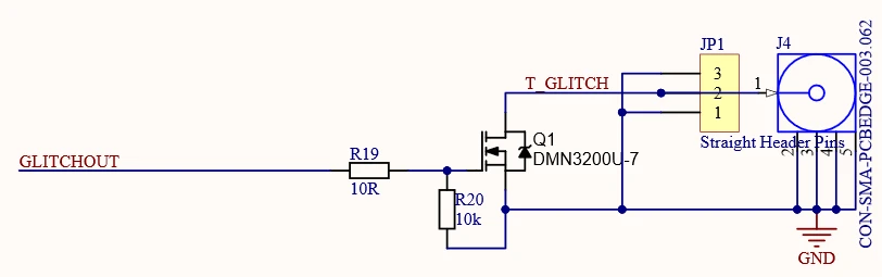
The middle pin on the header is not the glitch signal, it's supposed to be the voltage we want to short to ground, i.e. our Arduino 5V. We can actually see the the glitch pulse on the gate pin of the DMN3200U-7 transistor (the pin marked with a white dot on the silkscreen).

Thank you Nicolas Jurquet
How to prepare an Arduino Target
Chapter 9 (specifically p. 275) of Hardware Hacking Handbook explains it well.
Dismount the ATmega328p from the Arduino devboard and mount it on a breadboard. From the devboard, retrieve the following signals:
| Function | Devboard | Breadboard | ATmega328p |
|---|---|---|---|
| Reset | Reset | - | Pin 1 |
| 5V | 5V | Anywhere | Pin 20 |
| GND | GND | Anywhere | Pin 22 & 8 |
| Default TX | TX0 | - | Pin 2 |
| Default RX | RX0 | - | Pin 3 |
| Crystal | Pin 9 on ATmega header | - | Pin 9 |
| Crystal | Pin 10 on ATmega header | - | Pin 10 |
Add an RC pi filter with a large 330µF capacitor on one side and 100µF on the other, and a 100Ω resistor in-between. Add a 100Ω shunt between the filtered VCC and pin 7 on the ATmega.
Your probe for a power analysis would be on ATmega pin 7.
You would also need a trigger for the chipwhisperer. In the above diagram, it's on ATmega pin 4 because the code behaved so. It might not be the case on your target, use a pin that is relevant 🐧
Also, the serial communication for the password prompt would need to be connected to the chipwhisperer.