Detecting objects with YOLO - ori-systems/work_experience GitHub Wiki
In this chapter we will extend the navigation by sending the robot to an three-dimensional object pose detected by YOLO with an Intel Realsense depth camera.
Testing the camera
Before starting to code let's make sure that the Intel Realsense D435/D435i camera is working correctly. For this purpose follow the installation instructions given on the official Intel Realsense repository.
Exercise 1: Testing the camera
Connect the Realsense camera to your computer and launch it by opening a terminal and typing:
roslaunch realsense2_camera rs_camera.launch
This will spin up the camera driver.
Now check the camera output with rqt_image_view:
rosrun rqt_image_view rqt_image_view
You should be able to visualize the color and depth images outputted by the Realsense camera as described here.
Subscribing to the camera
Now we want to take it a step further and subscribe to the information published by the camera, namely the images, directly.
Exercise 2: Subscribing to the images
Let's start off by modifying the basic example for a subscriber that can be found here so that it subscribes to an image stream and outputs a string message whenever a new message is received. In order to change the topic that it subscribes to easily, the Python library argparse comes in handy.
Exercise 3: Plot the images with Matplotlib
Now as a next step we want to plot the images with the popular Python library Matplotlib. For this we will have to convert the received message using the cv_bridge package as described here. Finally we can display the resulting numpy construct with matplotlib as described here.
Detecting objects with YOLO
Now it is time to detect objects in the individual frames of the video. This is done by running an object detection on every single frame of the RGB image received from the depth camera.
Exercise 4: Understand the code
There is a good and yet simple tutorial available that explains how Yolo can be run with OpenCV. Read through the tutorial and try to understand what the code does. Read up on why a transformation to image blobs is performed.
Exercise 5: Launch the object detection on a static image
Finally clone the tutorial onto your machine with
git clone https://github.com/rasql/opencv-tutorial
and run it. Depending on your version of OpenCV you might have to adapt the script to your version of OpenCV. The configuration files for Yolo V3 can be found here:
| File | Download link |
|---|---|
| Class names | https://raw.githubusercontent.com/pjreddie/darknet/master/data/coco.names |
| Yolo V3 config | https://github.com/AlexeyAB/darknet/blob/master/cfg/yolov3.cfg |
| Yolo V3 weights | https://pjreddie.com/media/files/yolov3.weights |
Play around with the script, try different configuration and weights, e.g. the more recent Yolo V7
| File | Download link |
|---|---|
| Yolo V7 config | https://raw.githubusercontent.com/AlexeyAB/darknet/master/cfg/yolov7.cfg |
| Yolo V7 weights | https://github.com/AlexeyAB/darknet/releases/download/yolov4/yolov7.weights |
| Yolo V7 tiny config | https://raw.githubusercontent.com/AlexeyAB/darknet/master/cfg/yolov7-tiny.cfg |
| Yolo V7 tiny weights | https://github.com/AlexeyAB/darknet/releases/download/yolov4/yolov7-tiny.weights |
For it to work with newer versions of Yolo you will likely have to update the OpenCV Python3 package.
Exercise 6: Visualizing the detections on the camera image
Now let's integrate the object detection code into our ROS code so that the camera callback is combined with the object detection. For this purpose combine the code above with your camera subscriber node. Think thoroughly about if the corresponding variables should be part of the initializer of the class or of the method itself.
Estimating the depth of the detected objects
Our camera is actually not just a regular RGB camera but an RGB-D camera where the D stands for depth. It gives us not only an RGB-image but instead also an additional depth image. Stereo depth cameras work very similar to our own two eyes. With the help of the two different viewpoints of our eyes, we are able to perceive the depth of objects. For this purpose we will have to find the corresponding pixel in both images and use this information to geometrically reconstruct the depth. This can be done in different ways, from just taking the pixel whose colours matches best to more complex optimization problems. Additionally many stereo cameras offer active stereo, where a structured light grid (infrared) is projected into the scene to improve the depth estimate.
| Left image | Right image | Depth estimate SAD and WTA | Depth estimate with NCC and SGM |
|---|---|---|---|
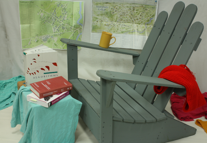 |
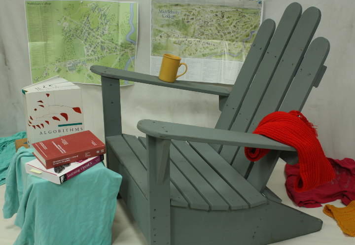 |
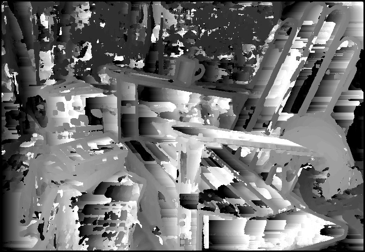 |
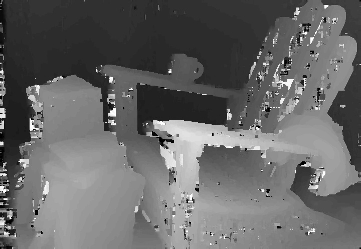 |
A code example of how this can be done can be found here.
Exercise 7: Update the callback to take multiple time-synchronized messages
Now we will have to subscribe to multiple messages at once. This can be done with a time synchronizer from the message_filters library. An example of this can be found here for Python. We are interested in using an approximate time policy like in this example. In our case we would like to subscribe to the RGB image, the depth image as well as the camera info. Update the callback accordingly.
Exercise 8: Determine the depth of an object
Determine the depth of the detected object by cropping out the detection box of the original image and then estimating the depth from all the pixels of the bounding box with an appropriate filter such as the median.
For this to work properly we will have to force the Realsense camera to align RGB and depth images. This can be done by specifying the following arguments:
rosrun realsense2_camera rs_camera.launch enable_pointcloud:=true align_depth:=true
or alternatively using the launch file rs_aligned_depth:
rosrun realsense2_camera rs_aligned_depth.launch enable_pointcloud:=true
Exercise 9: Determine the 3D pose of the object
Now we have a depth value associated with the pixel coordinates of the detection. We can use now basic trigonometry and physics, namely the pinhole camera model for determining the depth of the image. Try to derive the corresponding formula by reading through the Wikipedia. The focal length and center of the image can be extracted from the camera info topic. Read through the available documentation to find out how these parameters can be extracted.
Exercise 10: Publish the detected transform and visualize it in Rviz
We can now publish the 3D pose of the objects and visualize them in Rviz to see if they align with the point cloud. The following tutorials explain how this can be done either with the tf package or the tf2_ros package.
Commanding the robot to the detected objects
Finally let's send the robot to the detected pose. For this we will have to calculate the transform in a different frame, the map frame, as this is where the standard move_base toolchain expects them to be in.
Exercise 11: Transform listener
For this purpose we will have to convert the transform from the frame of the camera to the map frame. This can be done with a transform listener. Follow the example here to get the transform in between map and camera frame. Double check the result with the tf_echo tool:
rosrun tf tf_echo frame_1 frame_2
Finally chain the transformation from the camera to the object with transformations.py that is part of tf. Finally publish the resulting combined transform to see if it is correct.
Exercise 12: Command the robot with move_base
Finally we can send the robot to the detected pose with move_base. How this can be done is documented here.
For sending the robot to the final pose we will have to send a valid orientation. If the point is correct but the orientation is not, the robot will immediately turn down the given goal. Ideally we would want to offset the detection by a given distance so that the robot does not run over the object.