BASIC TOOLS FOR ENGINEERS - openhorizonrobotics/ece-1 GitHub Wiki
We have discussed various components such as resistors, capacitors, inductors, potentiometers, LEDs and serveral concepts like Current, Voltage , Resistance. But we don't know how to measure any of these. To do so, there are various tools such as Ammeters to measure current, Voltmeter to measure Voltage etc.
The most commonly used tool by engineers is the Multimeter , which can be used to measure a variety of parameters such as Current, Voltage, Resistance, Continuity and elimintates the need for individual tools for each . In this section we'll discuss how these tools work and how are different parameters measured in an electrical circuit.
The Ammeter:
Ammeter is a device used to measure either alternating or direct current. We know that ampere is the unit of current. Since this device measures the value in amperes, it’s known as ammeter. To measure the current, generally the ammeter is connected in series with the circuit. This device is mainly used for measuring a small amount of current, and the current is measured in the milliampere or microampere range. The device which is used to measure the current in milliampere is known as milliammeter, and the device for measuring extremely small electric currents, calibrated in microamperes is called microammeter. In a circuit, the ammeter is represented by the letter “A”. Ammeter always offers low resistance, and zero internal resistance is offered by an ideal ammeter.
Ammeter is connected in series in a circuit because Current is the same at all points in a series circuit. By connecting the ammeter in series, it measures the entire current flowing through the component or branch. If the ammeter were connected in parallel, it would not measure the actual current through the component.
Here's a simple circuit with an Ammeter connected in series with a batttery and a bulb.
The Voltmeter:
A voltmeter, also known as a voltage meter, is an instrument that measures the voltage or potential difference between two points of an electronic or electrical circuit. In order to measure a device’s voltage, a voltmeter is connected in parallel to a device. This setup is important as objects in parallel usually tend to experience the same potential difference. It is connected in parallel with the circuit, mainly because the same voltage drop occurs across it. A voltmeter also has high internal resistance. This is done mainly because it is used in measuring the potential difference between the two points of the circuit. As such, the current of the measuring device remains the same. In other words, the high resistance of the voltmeter will impede the flow of current through it. This allows the device to take correct readings of the voltage. The voltmeter is usually represented by the letter V, which is placed inside a circle adjoining two terminals. Here's a simple circuit with a Voltmeter connected in parallel with a battery and a bulb:
The Multimeter:
A multimeter or a multitester, also also called a VOM (volt-ohm-milliammeter), is an electronic measuring instrument that performs several measurement functions in one unit. A typical multimeter can be used to measure voltage, current and resistance and even to check for conductivity.
Main Components of a Multimeter
The main components of a multimeter are explained below:
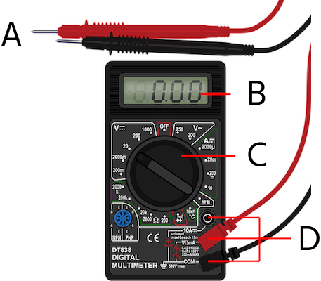
1. Selection Knob (A)
- The knob comes with an arrow pointer at its end to choose the parameter being measured (e.g., voltage, current, or resistance).
2. Display Panel (B)
- The display is a liquid crystal display (LCD), capable of showing up to four digits under normal circumstances.
- It also has the provision to display a negative sign.
3. Ports (C)
- There are three main ports on the front panel of a multimeter:
- COM: Symbolizes COMMON and is typically used to connect the ground or negative part of the circuit.
- VΩmA: Enables the measurement of voltage, current (up to 200mA), and resistance.
- 10A: A special port used to measure large currents (typically greater than 200mA).
4. Probes (D)
- A multimeter typically comes with two insulated probes:
- Red Probe: The plug of the red probe is connected to the VΩmA port, and its lead is connected to the positive terminal of the device under test (DUT).
- Black Probe: The plug of the black probe is connected to the COM port, and its lead is connected to the negative terminal of the DUT.
- Other than the color, there is no functional difference between the red and black probes.
Diagram
The main components of a multimeter are illustrated in the figure below.
Using a Multimeter:
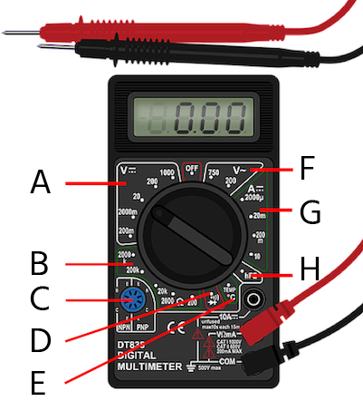
The front panel of the multimeter includes various functionalities to aid in measuring different parameters, as listed below:
-
A: DC Voltage
Used to measure direct current (DC) voltage. -
B: AC Voltage
Used to measure alternating current (AC) voltage. -
C: Current
Used to measure electric current. -
D: Transistor Gain (hfe)
Measures the current gain (hfe) of a transistor. -
E: Temperature
Measures temperature (usually in degrees Celsius or Fahrenheit). -
F: Continuity Check
Used to check the continuity of a circuit (audible buzzer when continuity is detected). -
G: Resistance
Measures resistance in ohms (Ω). -
H: Mounting Space for Transistor Terminals
Includes mounting space for emitter, base, and collector terminals of a transistor for testing purposes.
How to Measure Voltage with a Multimeter
-
Select the Voltage Range
- Rotate the knob to select a value under which the designated voltage may lie.
-
Connect the Probes
- Connect the red probe to the positive terminal and the black probe to the negative (or ground) terminal.
-
Adjust the Range
- Ensure the correct range is selected.
- Tip: Start with the highest range and gradually lower it if needed.
-
Read the Display
- The display will show the voltage across the leads.
Example
To check if a mobile phone battery is at fault:
- Connect the battery to the red and black probes.
- Rotate the knob to select 20V (as the expected voltage is around 5V, so a higher value needs to be chosen).
- Adjust the range as required and read the voltage value.
Note:
- For DC voltage, select the appropriate DC range.
- For AC voltage (e.g., an electrical plug), rotate the knob to select V~ (AC voltage symbol).
How to Measure Current with a Multimeter
-
Select the Current Range
- Twist the knob and select from the ranges of current displayed on the panel.
-
Connect the Probes
- For current greater than 200mA, connect the red probe to the 10A jack.
-
Adjust the Range
- Start with the highest range and reduce it if needed.
-
Read the Display
- The display will show the current value across the leads.
How to Measure Resistance with a Multimeter
-
Connect the Resistor
- Connect the resistor across the red and black probes.
-
Select the Resistance Range
- Rotate the knob to point to one of the resistance ranges on the front panel (start with the highest value).
-
Adjust the Range
- The selected range should always be greater than the resistor value being measured.
- Use trial and error to adjust the range for an accurate reading.
-
Read the Display
- The display will show the resistance value measured across the leads.
Comparison to Manual Method
Using a multimeter is faster and more accurate than using the BBROY color-coding method for resistors.
Multimeter Continuity Test
The continuity test function of a multimeter is used to check if there is a viable connection between two points in a circuit. This feature is particularly useful for debugging circuits and identifying connection errors.
Steps for Continuity Testing
-
Select Continuity Mode
- Rotate the knob to select the symbol resembling a propagating sound wave.
- This enables the continuity check mode.
-
Verify the Mode
- In this mode, when the probes touch each other, the multimeter emits a beep sound, indicating a closed connection.
-
Test the Connection
- Touch one probe to Point A and the second probe to Point B.
- If a beeping sound is made, it confirms that the two points are connected.
-
Read the Display
- The display panel will show the resistance across the points being tested.