EN Assembly of components (circuit) - opendata-stuttgart/meta GitHub Wiki
Language: DE
| Previous page | Next page |
|---|---|
| Installing firmware | Assembly of parts |
These instructions are for Version 3 of the NodeMCU (identification described in previous article). In Version 1 and Version 2 you have to use VIN and GND next to the MicroUSB connection, instead of VU and G.
!! Important !! Firmware has to be installed before using the SDS011. Only then will the outputs have defined levels.
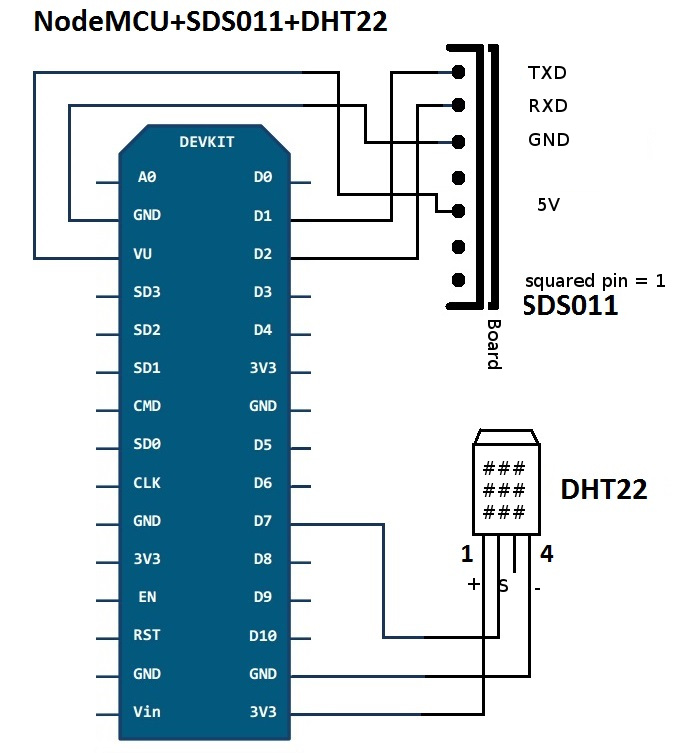
Circuit diagram
Below the circuit diagram of how to connect NodeMCU, SDS011, DHT22. It's recommended to use Jumper wires (DuPont cables) of approx. 20cm length - see shopping list. Optionally and also proven more successful with installs is to also connect Pin1 of the DHT22 to 5V (VU). For example with a Y-DuPont cable - see Assembly of parts.
Connections
Connections SDS011
The pins are listed from right to left. When connecting the cables, make sure the connectors are actually on the pins, since DuPont plugs fit in-between as well.
| SDS011 pin | NodeMCU pin |
|---|---|
| 1 | D1 (GPIO5) |
| 2 | D2 (GPIO4) |
| 3 | GND |
| 4 | unused |
| 5 | VU |
| 6 | unused |
| 7 | unused |
Connections DHT22
The pins are listed from left to right. The grid is front-facing.
| DHT22 pin | NodeMCU pin |
|---|---|
| 1 | 3V3 (3.3V) |
| 2 | D7 (GPIO13) |
| 3 | unused |
| 4 | GND |
Other sensors and hardware
Connections PPD42NS
The pins are listed from right to left.
| PPD42NS pin | NodeMCU pin |
|---|---|
| 1 | GND |
| 2 | D5 (GPIO14) |
| 3 | VU |
| 4 | D6 (GPIO12) |
| 5 | unused |
Connections I2C hardware (eg. barometric pressure BMP180, display, ...)
The firmware can read IC2 hardware that is connected as follows. It has to support 3.3V.
| IC2 | NodeMCU pin |
|---|---|
| Vcc | 3V3 |
| Gnd | GND |
| SDA | D3 (GPIO0) |
| SCL | D4 (GPIO2) |