Cache and low latency - oleksiyp/oleksiyp.github.io GitHub Wiki
2012 Sandy Bridge E class servers our memory hierarchy can be decomposed as follows:
Registers: Within each core are separate register files containing 160 entries for integers and 144 floating point numbers. These registers are accessible within a single cycle and constitute the fastest memory available to our execution cores.
Memory Ordering Buffers (MOB): The MOB is comprised of a 64-entry load and 36-entry store buffer. These buffers are used to track in-flight operations while waiting on the cache sub-system as instructions get executed out-of-order. The store buffer is a fully associative queue that can be searched for existing store operations, which have been queued when waiting on the L1 cache. These buffers enable an ordered view of the world to be re-constructed for what is expected according to the memory model.
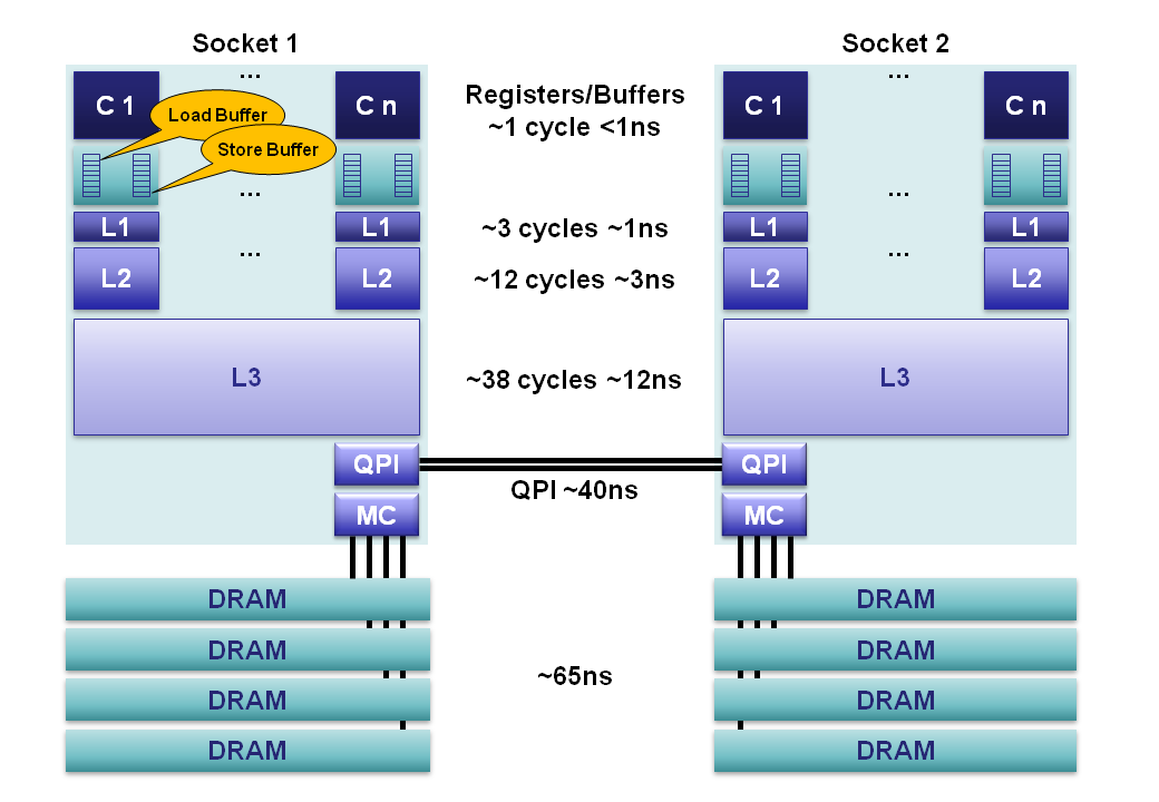
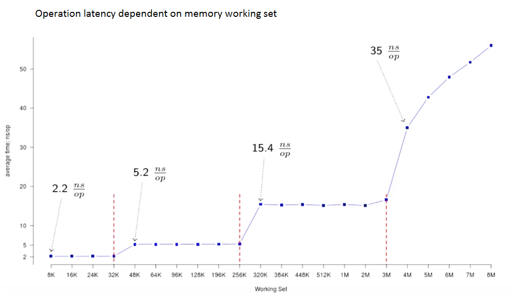
Level 1 Cache: The L1 is a core-local cache split into separate 32K data and 32K instruction caches. Access time is 3 cycles and can be hidden as instructions are pipelined by the core for data already in the L1 cache.
Level 2 Cache: The L2 cache is a core-local cache designed to buffer access between the L1 and the shared L3 cache. The L2 cache is 256K in size and acts as an effective queue of memory accesses between the L1 and L3. L2 contains both data and instructions. L2 access latency is 12 cycles.
Level 3 Cache: The L3 cache is shared across all cores within a socket. The L3 is split into 2MB segments each connected to a ring-bus network on the socket. Each core is also connected to this ring-bus. Addresses are hashed to segments for greater throughput. Latency can be up to 38 cycles depending on cache size. Cache size can be up to 20MB depending on the number of segments, with each additional hop around the ring taking an additional cycle. The L3 cache is inclusive of all data in the L1 and L2 for each core on the same socket. This inclusiveness, at the cost of space, allows the L3 cache to intercept requests thus removing the burden from private core-local L1 & L2 caches.
Main Memory: DRAM channels are connected to each socket with an average latency of ~65ns for socket local access on a full cache-miss. This is however extremely variable, being much less for subsequent accesses to columns in the same row buffer, through to significantly more when queuing effects and memory refresh cycles conflict. 4 memory channels are aggregated together on each socket for throughput, and to hide latency via pipelining on the independent memory channels.
NUMA: In a multi-socket server we have non-uniform memory access. It is non-uniform because the required memory maybe on a remote socket having an additional 40ns hop across the QPI bus. Sandy Bridge is a major step forward for 2-socket systems over Westmere and Nehalem. With Sandy Bridge the QPI limit has been raised from 6.4GT/s to 8.0GT/s, and two lanes can be aggregated thus eliminating the bottleneck of the previous systems. For Nehalem and Westmere the QPI link is only capable of ~40% the bandwidth that could be delivered by the memory controller for an individual socket. This limitation made accessing remote memory a choke point. In addition, the QPI link can now forward pre-fetch requests which previous generations could not.