Ws2812b - ntim/hyperion GitHub Wiki
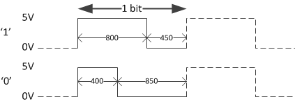
| T0H | 400ns | ±150ns |
| T0L | 850ns | ±150ns |
| T1H | 800ns | ±150ns |
| T1L | 450ns | ±150ns |
| RES | >50us |
This timing is also shown in the following image:
To accomplish the required block waves the 'Mini UART' on the GPIO of the Raspberry PI is used. This is a RS232 device without any levelshift (eg between -12V and +12V, or TTL), the levels are therefore 0V and 3.3V. The idea is to transmit a '1' on the TX-line when the signal needs to be high and a '0' when the signal needs to be low. On the UART port each byte is send with one start bit (which is high) an optional parity bit (which depends on the number of high bits) and one or two stop bits (which are low). For the control of the WS2812b the output is set to '7N1'. This means each byte is 7 bits long, there is no parity bit and there is 1 stop bit. The RS232 will thus generate 9 bits for each 7 bits transmitted (start and stop bit are generated by the device). By default the TX is high (3.3V) when idle. Because we require the TX line low when idle to latch the set values, inversion is required. Inversion can of course be done with an inverter (74HCT04) but a NAND (74HCT00) or NOR (74HCT02) will work just as well. Note that it is important to use a chip from the HCT version as these are compatible with the 3.3V inputs of the Pi.
Note that a baudrate of 2.5MHz gives a correct match with the required timing. However it turns out that at 2MHz the Ws2812b, although not within specs, still works correctly. Because the UART transmit buffer of the RPi is only 8 bytes long, the lower the baudrate the less change of having a buffer underrun. During testing it appeared that this was probably still not low enough because now and again, though less frequent, glitches were observed.
Default the mini UART is mapped to '/dev/ttyAMA0' which is again set as a debug console. You can connect the mini UART to another PC's serial port and open a terminal session over it. This can be used for debugging your system if all other connection fail. For the WS2812b to work with the mini UART, this debug console should be disabled. This is done by deleting or moving the file '/etc/init/ttyAMA0.conf'. A second thing to be configured is the base baudrate of the UART clock. This base rate defines the maximum possible baudrate and is at a factor 16 higher then the maximum possible baudrate. This base baudrate can be configured by adding the following line to '/boot/config.txt': ``` init_uart_clock=128000000 ``` Note that this is actually 64 times the required baudrate of 2MHz. This is because originally we wanted to implement a 10bits encoding scheme instead of a 3bits encoding. There are specifications for the WS2811 and WS2812 that do not translate to a 3bit encoding scheme.The 10bits encoding would require a baudrate of 8MHz. However linux by default has a maximum of 4MHz defined in its kernel. To use a higher baudrate a custom configuration is required which we did not get working for the moment. However it should be possible and if we succeed we would like to use the same encoding for all WS2811 based devices.