Instrument panel - ntb001/rear-fog GitHub Wiki
Installing the Instrument Panel indicator
One of the early sparks for this project was noticing that the rear fog indicator symbol was etched into the instrument panel next to the rest of the light indicators.
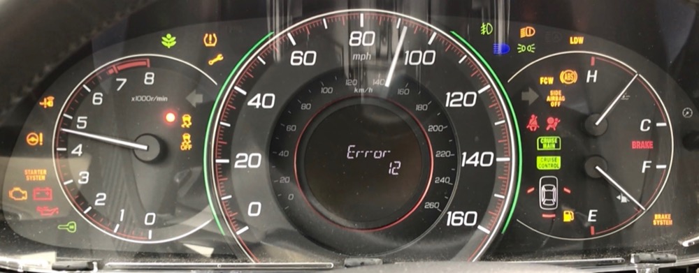
A picture of the IP Sweep Test in progress. The rear fog indicator is surrounded by the error, running, high-beam, and front fog indicators.
Taking apart the IP reveals the LEDs are surface mounted on the circuit board. A white plastic spacer connects the board to the face of the panel. The spacer has a honeycomb-like structure that separates the individual LEDs and prevents one from bleeding into another's etching. Luckily, the rear fog indicator is located on the outer edge of the IP, so we can drill into the spacer and add our own LED.
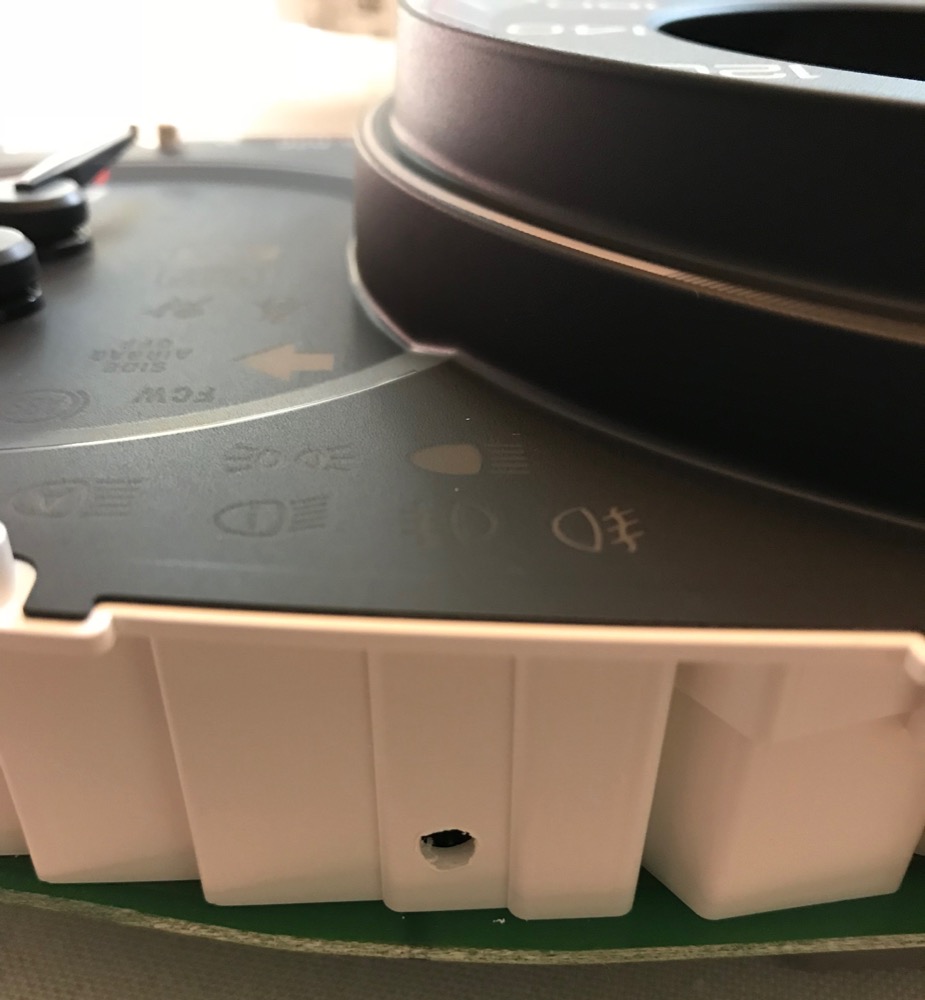
A hole drilled into the spacer. The symbols are faintly visible on the panel face.
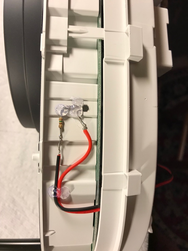
A yellow LED is used to achieve the correct color. The correct resistor is added to account for the 5V it will receive from the output pin of the Arduino. The LED is hot glued in place and the wire is routed out the back of the IP and through the dash to the controller.
The new LED is brighter than the rest of the panel. The Arduino can use PWM to make the LED appear dimmer (Arduino PWM). The program brightness_test was written to help identify the correct analogWrite values to match the various brightness levels of the IP. The IP has a daytime/max brightness level and can be manually dimmed in nighttime mode.
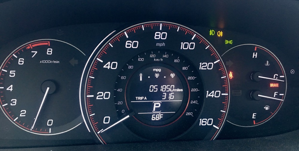
Headlights, front fogs, and rear fog all illuminated.