Working with Signal Attributes template - nsrr/edf-editor-translator GitHub Wiki
EDFHeader: Signal Attributes
View Signal Attributes
-
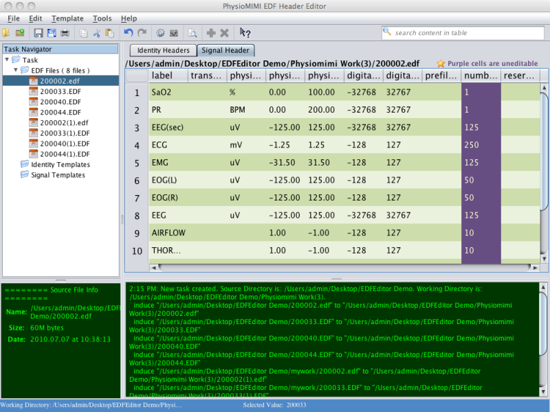
The Signal Attributes for a single opened EDF file can be viewed by clicking the file name from the list of open EDF files in the Task Navigator, or by clicking the Signal Attributes tab in the Data Workspace.
-
Signal attributes are displayed as a grid with the channels as rows and the attributes as columns. The width of columns can be adjusted by clicking and dragging the column heading boundaries.
EDF Signal Attributes
Edit Signal Attributes
- Manual Edit
- Values can be edited by double-clicking in the desired cell and typing or pasting a new value.
- Note that certain fields can be viewed but are not available for editing. These fields are displayed in black. Manual editing of certain fields could cause data integrity conflicts that could render the EDF file useless.
- The Transducer Type field will be used to hold a standardized signal type name, which is a combination of a procedure, a device, a location (when applicable), and a reference location (when applicable). To facilitate creating these standard signal types, a Create Transducer Label expression builder has been built into the editor. The builder is launched by pressing and holding the ALT-key and clicking on the Transducer Type field in the Signal Attributes grid (see section 'Transducer Label Expression Builder' for more information).
- Apply Signal Attribute Template
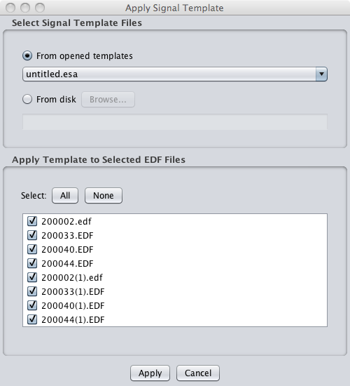
- Values can also be modified for all files simultaneously by applying a Signal Template. These template files contain values or keyword instructions that are applied to each file. A template can be applied by selecting the
Template > Apply Signal Templatemenu item or by clicking the apply template taskbar icon. - A currently open template file can be selected from the list, or the user can browse for an existing template file. The files to which the template will be applied can be configured by selecting and deselecting individual files.
- Because the application of a template edits every selected file, it is important that these templates be properly configured (see #EDFHeader: Configuring Signal Attribute Templates).
Applying Signal Attributes
- Undo Changes
- Before changes are saved to the files they can be undone by selecting the
Edit > Undomenu item or clicking the undo taskbar icon. This will restore the value before the last edit. - To undo all changes since the last save, select
Edit > Discard Changes. All signal attributes will be restored to the values at the time of the last save.
- Save Changes
- All changes can be saved by selecting the
File > Savemenu item or clicking the save taskbar icon. This will write any changes made to the Identity Attributes or the Signal Attributes to the output EDF files. - Note that if you are not overwriting existing files, the first time changes are saved the output files must be created.
- If the files are large and/or a large number of files was selected this process can take several minutes.
- During this process the entire EDF file (the header as well as the signal data) is being written to disk in the selected output directory. The task progress bar will indicate that the program is executing the save process.
- Subsequent changes, since they only involve modifying the header of each file and not the signal data, are very quick.
Configuring Signal Attribute Templates
The purpose of Signal Template files is to provide a mapping between signal labels and standardized attributes which can then be used to modify the values for signals in individual EDF files. A Signal Template may contain many more channels than are found in any particular file, and in this respect it is more of a mapping or a lookup file. Because the order of channels can change from study to study, the label is used as the lookup for the Signal Template, and the order of signals in the template does not matter. When applied, for each channel in each file the EDF Editor will attempt to find a corresponding label in the selected Signal Template. If a match is found the other attributes (Transducer Type, Physical Dimension, Physical Minimum, Physical Maximum, Digital Minimum, Digital Maximum) will be inserted for that channel, overwriting the original values. If a particular channel label is not found in the template its values are retained.
The physical dimension and the physical and digital ranges are essential to the proper interpretation of the resulting EDF file, and must be completed with great care. EDF files generated by some vendors are populated with incorrect values for the physical range and dimensions. Users are encouraged to consult PSG technicians to determine the appropriate collection settings for each signal.
The current version of the EDF Editor now contains an additional column for a corrected label. This allows users to rename channels to standard names by means of a template.
Signal Template files are ASCII-based files saved with the extension .esa (EDF Signal Attributes).
EDF Signal Attributes Template

- Open Existing Template
- An existing template file can be selected for editing by selecting the
Template > Open Signal Templatemenu item and browsing for the appropriate file on the disk.
- Create New Template
- A new template can be created by scratch by selecting the
Template > New Signal Templatemenu item. - This presents the user with a blank grid of the Signal Attributes template fields with only one row. New rows can be inserted by selecting the
Edit > Add rowmenu item or clicking the new row taskbar icon. The currently-selected row can be deleted by selecting the Edit > Remove row menu item or clicking the remove row taskbar icon.
- Import Template from EDF
- A new template can also be created by importing the values from the header of an existing EDF file. This can be used as a starting point and then the attributes of the template modified as necessary before saving.
- Save Template
- Signal Template files can be saved by selecting the
File > Savemenu item or clicking the save taskbar icon. Files can be saved with a new file name by selecting theFile > Save as ...menu item.
EDFHeader: Transducer Label Expression Builder
Transducer Label Expression Builder
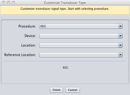
The Transducer Type field will be used to hold a standardized signal type name, which is a combination of a procedure, a device, a location (when applicable), and a reference location (when applicable). To facilitate creating these standard signal types, a Create Transducer Label expression builder has been built into the editor. The builder is launched by clicking on the Transducer Type field in the Signal Attributes grid.
The standard signal type label is built by selecting a procedure, device, and location(s) as indicated. The lists update automatically based on the choice of procedure.
Currently the following procedures with their associated devices and locations are included in the expression builder. All of the combinations within a procedure can be executed using the builder. Future versions of the EDF Editor will include additional data to make the lists as comprehensive as possible.
| Procedure | Devices | Locations |
| Body Position | AccelerometerMercury SwitchTechnician Observation | |
| Capnography Wave Form | Capnograph | |
| Carbon Monoxide Monitoring | CapnographEnd-tidal CO2Transcutaneous CO2 | |
| ECG | Electrode (Surface)Electrode (Subdermal) | 12-lead: Lead I (RA-LA)12-lead: Lead II (RA-LL)12-lead: Lead III (LA-LL)12-lead: Left Arm (LA)12-lead: Left Leg (LL)12-lead: MCL112-lead: Right Arm (RA)12-lead: Right Leg (RL)12-lead: V112-lead: V212-lead: V312-lead: V412-lead: V512-lead: V6Left SubclavicalRight Subclavicallower rib |
| EEG | Electrode (Surface)Electrode (Subdermal) | A1, A2, C1, C2, C3, C4, C5, C6, Cz, F1, F2, F3, F4, F5, F6, F7, F8,F9, F10, Fz, O1, O2, Oz, P1, P2, P3,P4, P5, P6, P7, P8, P9, P10,Pz, T3, T4, Forehead |
| EMG | Electrode (Surface)Electrode (Subdermal)Piezoelectric Sensor | ChinChin (Central)Chin (Left)Chin (Right)Left LegRight Leg |
| EOG | Electrode (Surface)Electrode (Subdermal) | HEOGLeft Eye (LVEOG, LOC)Right Eye (RVEOG, ROC) |
| Esophageal Manometry | ||
| Esophageal pH Test | ||
| Light Monitoring | Light SensorTechnician Observation | |
| Movement | AccelerometerTechnician Observation | |
| Oximetry | Pulse OximeterTranscutaneous O2 | FingerToe |
| Plethysmography | Pulse Oximeter | |
| Positive Airway Pressure | CPAP Mask | |
| Pulse Rate | Pulse Oximeter | |
| Respiratory Effort | Impedance BeltInductance BeltPiezoelectric BeltStrain Guage | AbdomenChestSUM of Chest and Abdomen |
| Respiratory Flow | CPAP MaskExpired Carbon DioxideIntranasal Pressure TransducerNasal CannulaPneumotachometerThermistorThermocouple | MouthMouth / NoseNose |
| Snoring | MicrophoneTechnician Observation |