Example 1 mininet wifi - nps-ros2/mininet_testbed GitHub Wiki
In this example we define a swarm consisting of a ground station (GS) robot R1 and four red_team robots R2 through R5. The ground station is publishing collective odometry information to the red team robots at 10 Hz. The publisher and the subscriber for the odometry topic both use the same QoS policy.
Define Scenario messages
Define publication and subscription parameters for the odometry topic and assign them to roles GS and red_team. Then assign these roles to specific robots in our swarm. When the simulation starts, communication will flow between these robots as allowed by their network configuration. Here is the CSV communication setup file for this example, named example1.csv:
# Publisher, Role, Topic, Frequency, Size, History, Depth, Reliability, Durability
Publisher, GS, odometry, 10, 500, keep_last, 0, reliable, volatile

# Subscribers, Role, Topic, History, Depth, Reliability, Durability
Subscriber, red_team, odometry, keep_last, 0, reliable, volatile

# Robot, Name, Role
Robot, R1, GS
Robot, R2, red_team
Robot, R3, red_team
Robot, R4, red_team
Robot, R5, red_team
Define the Scenario network configuration
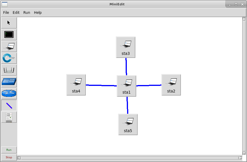
Define an ad-hoc network of five stations to support network traffic for the five robots needed in this example. Using miniedit, create a central station with four stations around it and define ad-hoc links between each:
- Click the station (laptop) icon
- Click the five places to drop three stations. You may need to adjust their positions later so they are in range of each other.
- Click the link (line) icon
- For each station, click down on one station, drag the cursor, and release the click on another station to connect stations with a link.
- Click the selection (arrow) icon
- Right click each link to define the connection type as ad-hoc and to set the source and destination properties for wlan0.
- Save the network as a Python script by selecting the File menu and selecting
Export level 2 script. For filename, typedemo1to save it asdemo1.py.
The view might look as follows:
screenshots/miniedit_wifi_example1.png
Here is the saved file:
#!/usr/bin/python

from mininet.log import setLogLevel, info
from mn_wifi.net import Mininet_wifi
from mn_wifi.node import Station, OVSKernelAP
from mn_wifi.cli import CLI
from mn_wifi.link import wmediumd, adhoc
from mn_wifi.wmediumdConnector import interference
from subprocess import call


def myNetwork():

    net = Mininet_wifi(topo=None,
                       build=False,
                       link=wmediumd,
                       wmediumd_mode=interference,
                       ipBase='10.0.0.0/8')

    info( '*** Adding controller\n' )
    info( '*** Add switches/APs\n')

    info( '*** Add hosts/stations\n')
    sta3 = net.addStation('sta3', ip='10.0.0.3',
                           position='376.0,104.0,0')
    sta5 = net.addStation('sta5', ip='10.0.0.5',
                           position='384.0,373.0,0')
    sta4 = net.addStation('sta4', ip='10.0.0.4',
                           position='204.0,235.0,0')
    sta1 = net.addStation('sta1', ip='10.0.0.1',
                           position='379.0,239.0,0')
    sta2 = net.addStation('sta2', ip='10.0.0.2',
                           position='534.0,235.0,0')

    info("*** Configuring Propagation Model\n")
    net.setPropagationModel(model="logDistance", exp=3)

    info("*** Configuring wifi nodes\n")
    net.configureWifiNodes()

    info( '*** Add links\n')
    net.addLink(sta1, cls=adhoc, ssid='new-ssid', mode='g', channel=1, intf='sta1-wlan0')
    net.addLink(sta2, cls=adhoc, ssid='new-ssid', mode='g', channel=1, intf='sta2-wlan0')
    net.addLink(sta1, cls=adhoc, ssid='new-ssid', mode='g', channel=1, intf='sta1-wlan0')
    net.addLink(sta3, cls=adhoc, ssid='new-ssid', mode='g', channel=1, intf='sta3-wlan0')
    net.addLink(sta1, cls=adhoc, ssid='new-ssid', mode='g', channel=1, intf='sta1-wlan0')
    net.addLink(sta4, cls=adhoc, ssid='new-ssid', mode='g', channel=1, intf='sta4-wlan0')
    net.addLink(sta1, cls=adhoc, ssid='new-ssid', mode='g', channel=1, intf='sta1-wlan0')
    net.addLink(sta5, cls=adhoc, ssid='new-ssid', mode='g', channel=1, intf='sta5-wlan0')

    net.plotGraph(max_x=1000, max_y=1000)

    info( '*** Starting network\n')
    net.build()
    info( '*** Starting controllers\n')
    for controller in net.controllers:
        controller.start()

    info( '*** Starting switches/APs\n')

    info( '*** Post configure nodes\n')

    CLI(net)
    net.stop()


if __name__ == '__main__':
    setLogLevel( 'info' )
    myNetwork()
Now edit this file to make it compatible with the mininet runner. Here, we additionally rename station names to robot names, change coordinates of stations, change the plot size, organize the code to be more readable, and remove some redundant addLink lines:
#!/usr/bin/python

from mininet.log import setLogLevel, info
from mn_wifi.net import Mininet_wifi
from mn_wifi.node import Station, OVSKernelAP
from mn_wifi.cli import CLI
from mn_wifi.link import wmediumd, adhoc
from mn_wifi.wmediumdConnector import interference
from subprocess import call


def myNetwork():

    net = Mininet_wifi(topo=None,
                       build=False,
                       link=wmediumd,
                       wmediumd_mode=interference,
                       ipBase='10.0.0.0/8')

    info( '*** Adding controller\n' )
    info( '*** Add switches/APs\n')

    info( '*** Add hosts/stations\n')
    R1 = net.addStation('R1', ip='10.0.0.1', position='0.0,0.0,0')
    R2 = net.addStation('R2', ip='10.0.0.2', position='1.0,0.0,0')
    R3 = net.addStation('R3', ip='10.0.0.3', position='0.0,1.0,0')
    R4 = net.addStation('R4', ip='10.0.0.4', position='-1.0,0.0,0')
    R5 = net.addStation('R5', ip='10.0.0.5', position='0.0,-1.0,0')

    info("*** Configuring Propagation Model\n")
    net.setPropagationModel(model="logDistance", exp=3)

    info("*** Configuring wifi nodes\n")
    net.configureWifiNodes()

    info( '*** Add links\n')
    net.addLink(R1, cls=adhoc, ssid='new-ssid', mode='g', channel=1, intf='R1-wlan0')
    net.addLink(R2, cls=adhoc, ssid='new-ssid', mode='g', channel=1, intf='R2-wlan0')
    net.addLink(R3, cls=adhoc, ssid='new-ssid', mode='g', channel=1, intf='R3-wlan0')
    net.addLink(R4, cls=adhoc, ssid='new-ssid', mode='g', channel=1, intf='R4-wlan0')
    net.addLink(R5, cls=adhoc, ssid='new-ssid', mode='g', channel=1, intf='R5-wlan0')

    net.plotGraph(min_x=-2, min_y=-2, max_x=2, max_y=2)

    info( '*** Starting network\n')
    net.build()
    info( '*** Starting controllers\n')
    for controller in net.controllers:
        controller.start()

    info( '*** Starting switches/APs\n')

    info( '*** Post configure nodes\n')

#    CLI(net)
#    net.stop()

    return net


if __name__ == '__main__':
    setLogLevel( 'info' )
    myNetwork()
Run the scenario:
Run the example scenario using the mininet runner, specifying the example1_mod.py Python network setup file, the example1.csv CSV communication setup file, and _mininet_test_outfile for the name of the new log output file:
cd ~/gits/mininet_testbed
./mininet_runner.bash scenarios/example1_mod.py scenarios/example1.csv _mininet_test_outfile
When the mininet_runner begins, it displays the contents of the CSV file, actions taken in setting up the network topology, and the commands used for starting the ROS2 robots in their respective network namespaces.
Also this graph opens showing the locations of the robots:
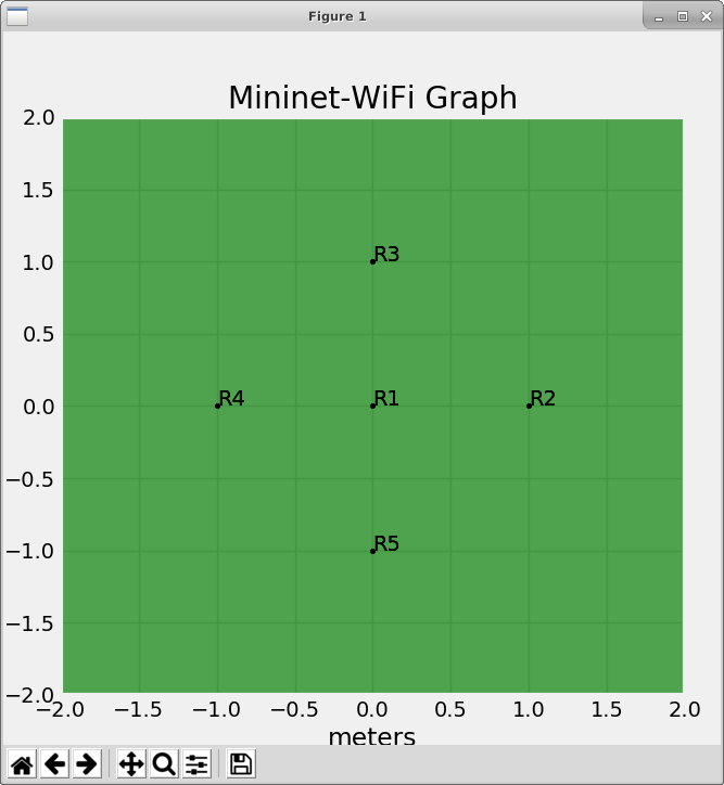
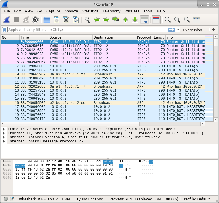
Also Wireshark opens within the Robot R1 network namespace. To observe flows, capture from the R1-wlan0 interface. In time, the ad-hoc network should connect and you should see the data packets that flow to and from R1. Here is an example capture of network traffic flowing at robot R1, showing RTPS traffic starting up 33 seconds after packet capture for R1-wlan0 was started:
screenshots/wireshark_snapshot.png
Plot results:
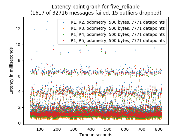
Plot the results of the example scenario simulation, naming them five_reliable and saving them with prefix five_reliable:
cd ~/gits/mininet_testbed
./plot_analytics.py _mininet_test_outfile five_reliable -w five_reliable
Here are the plots:
Latency points:
plots/five_reliable_latency_points.png
Throughput:
plots/five_reliable_throughput.png
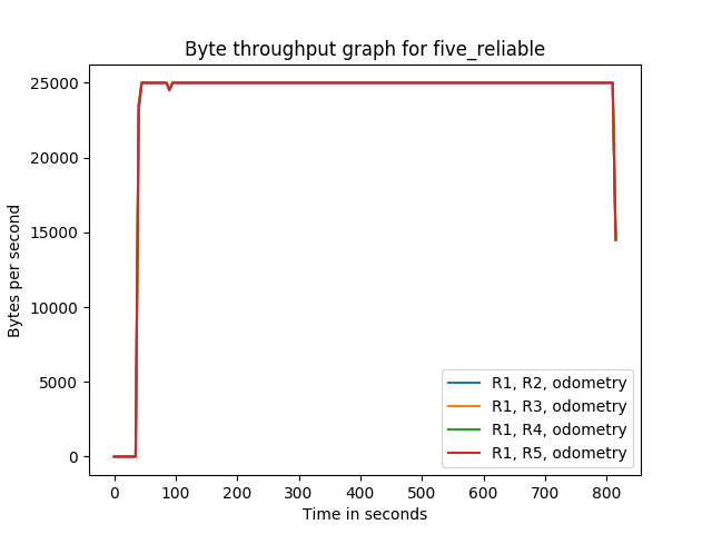
Latency:
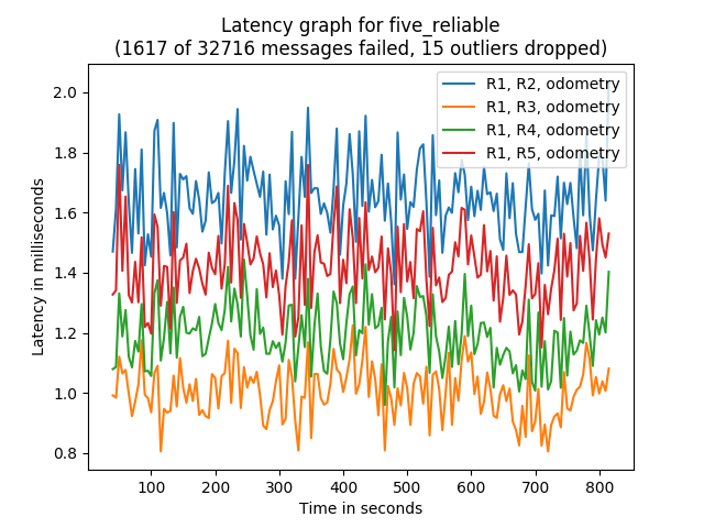