Pin Layout - notthesinger/ROV_Project GitHub Wiki
Over View
This page describes the pin lay out for all components and can be used to recreate the device from scratch, using the provided code!
LCD 2 X 16 display
VSS (GND) --> GND
VDD (+5 volts) --> +5 volts
Vo (LCD Contrast) --> out put of pentameter (Figure 1: pin 2)
RS (Register Select) --> pin 22
R/W (Read/Write) --> GND
E (Enable) --> pin 24
D4 (data bus) --> pin 26
D5 (data bus) --> pin 28
D6 (data bus) --> pin 30
D7 (data bus) --> pin 32
A (anode) --> +5 volts
K (cathode) --> GND
10K Potentiometer
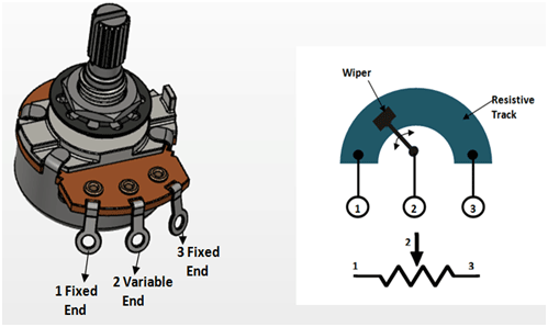 Figure 1: 10K Potentiometer
1 --> +5 volts
2 --> Vo (LCD Display)
3 --> GND
Rotary Encoder - Controlling Power
CLK --> pin 48
DT --> pin 46
SW --> pin 45
PWR --> +5 volts
GND --> GND