NIF Stereo Projector Calibration Guide - nimh-nif/SCNI_Toolbar GitHub Wiki
(Written by Aidan Murphy, March 2014)
The NIF’s stereo projection system is designed for presentation of stereoscopic stimuli. It was initially intended for use in binocular rivalry experiments (presentation of completely different images to each eye, which cannot be binocularly fused) but can potentially be used for 3D binocular disparity experiments (slightly shifted images in each eye, which can be fused) provided it is carefully calibrated. Although each projector can be used independently for regular stimulus presentation, the fact that the system is intended for stereo presentation introduces several caveats:
1. Both projectors must always be calibrated together, even if you only intend to use one of them. The reason for this is that any changes made to one projector will affect those variables relative to those of the other projector, and will thus be disruptive to any users conducting stereo experiments. For the purpose of any experiment involving stereoscopic presentation, matched calibration of various projector parameters is essential. Therefore, unless there is facility-wide consensus that the stereoscopic presentation capabilities are not being utilized, users should always calibrate both of the stereo projectors.
2. Experiments where color perception (and thus color calibration) is important cannot be performed. This is because the stereo projectors are fitted with INFITEC interference filters (Jorke and Fritz, 2003). Each projector’s interference filter allows three peak wavelengths of the visible spectrum to pass through it, corresponding to the tuning of primate cone receptors (RGB). Stereoscopic presentation is achieved because the peaks for each projector are offset (see figure 1), thus minimizing cross-talk. When viewed with both eyes through the corresponding A and B filters, full color images can be presented stereoscopically. However, when viewed through just one filter, the left eye image (top projector) appears slightly greenish and the right eye image (bottom projector) appears slightly reddish, due to the proximity of each band-pass peak with the corresponding peak sensitivity of cone receptors in the primate retina.

Calibration of the projection image size, position, shape, focus, and luminance are important for any visual experiment. By ignoring basic properties of the visual stimulation used during your imaging experiment, you will at best appear neglectful and unmethodical to reviewers, while at worst you will unwittingly introduce biases into you results. It is therefore the responsibility of individual experimenters to ensure that these features are correctly calibrated for each session. The following procedures are intended to make checking and adjusting projector calibration fast and easy, thus encouraging the maintenance of the projector system and benefiting all users.
This section briefly describes the projection and measurement equipment required for calibration of the projector systems in the NIF. PDFs of the equipment manuals should be located in the same directory as this document.
-
Navitar 2.75”-5.0” NuView Zoom lenses The Epson projectors are located approximately 3.05 m from the rear projection screen inside the bore of the scanner. The scanner bore is 0.4m in diameter, and the area visible to an animal inside the bore is further restricted by the headpost. Consequently, the projected image needs to be considerably smaller than would be typical
-
Neutral density filters The bright images projected by the Epsons are intended for large screens. Here, we instead focus the light onto a small area on the screen inside the bore, resulting in luminance intensities exceeding the limits of our photometer’s measurement capabilities (>1000cd/m2)! To compensate for this, we have attached neutral density (ND) filters, which are designed to attenuate luminance linearly across the spectrum. The strengths of neutral density filter available in the NIF are 0.9 ND (12.5% transmittance) and 0.6 ND (25% transmittance). The filters are fitted on the outside of the Navitar lens using custom-made plastic filter holders.
-
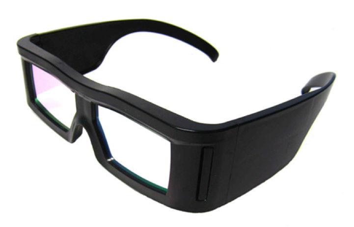
INFITEC filters In order to view the different interference filtered projector images in each eye, the viewer must wear a pair of INFITEC filter glasses. The curved glass filter lenses from three pairs of INFITEC Plus glasses have been removed and fitted into custom designed equipment:
- Binocular monkey goggles The binocular goggles attach to the front of the monkey chair, the same way as the regular mirror, and holds the components necessary for the monkey to view the screen inside the bore. A first surface mirror (Edmund Optics) with adjustable angle reflects light from the rear-projected image on the screen, towards the monkey’s eyes. The light passes through the two INFITEC filters, and is split by a central septum that separates the two channels. Finally, it passes through of a pair of hot mirrors angled at 45 to the line of sight (Edmund Optics), and into the monkey’s eyes. The hot mirrors reflect infrared light from IR diodes located at the sides, off the eye, and back into the MR compatible camera(s) (MRC), also located at the sides.

-
Luminance calibration filters In order to measure the luminance of the projected images as they will appear to the monkey, luminance measurements should be made through the INFITEC filters, and with both projectors turned on simultaneously. For this purpose, one of each filter has been fitted into holders that slot between the luminance probe and the test screen (Figure 3).
-
Spatial calibration binoculars In order for users to check the spatial alignment of the projectors, one pair of INFITEC Plus glasses have been kept intact. These can be used alone, or in combination with a pair of binoculars, to view the projected images on the screen inside the bore.
-
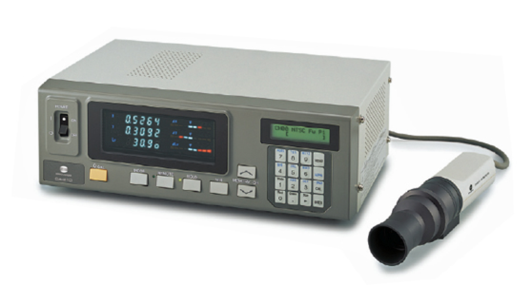
Photometer: Konica-Minolta CA-210 Color Analyzer CA-210 Universal measuring probe
- Distance measurement: Bosch DLR130 The Bosch DLR130 is a laser-based distance measurement device. It can be used to measure the exact distance from the projector to the screen (approximately 305cm), and then to place the test screen at the same distance, in order to make accurate luminance measurements outside of the magnet.
-
Video Connections Since the Epson projectors are located inside the RF shielded MR environment, they receive their DVI-D inputs through a pair of 40ft optical-fiber DVI cables, which run through the wave guide. At each end of each cable is an active (+5V DC) transmitter/ receiver that converts between the optical signal and the electrical DVI-D signal. This also reduces signal attenuation over the distance from the server room to the projectors. The source of the projector signal is the Nvidia GeForce GFX 650Ti graphics board installed in the Stereo_Stim workstation. Specifically, HDMI and/or DVI outputs from the graphics card are sent to a pair of StarTech ST122DVIA active DVI-splitters (each requiring 9V DC input), which split each output between one projector and one console room display.
-
Network Connections The Epson projectors feature browser-based control of basic remote functions (e.g. power on/ off). To allow these remote functions to be performed from the control room, each Epson projector must be connected to the network via the Ethernet port.
-
Serial Connections See section ‘3.2. Serial Connection’ below for information on serial connections between the photometer and the luminance measurement PC.
The strong magnetic field (4.7T) and narrow bore (40cm diameter) of the NIF’s Bruker pose some difficulty for calibration of projected images on the screen inside. For this reason, an alternative setup has been devised, in which the projection is reflected twice in order to project the images to a screen outside the bore where measurements can be more easily made and more closely inspected (see figure X).

The following procedure for calibration is based on the fact that the projection image is far easier to assess outside of the bore. However, there is no substitute for assessment of image quality inside the bore and by examining the behavioral responses of your monkey. Recreating experimental conditions outside of the bore for calibration requires careful replication of the same projection distance and ambient lighting. To this end, the distance between the projectors and test screen should be fixed at the same distance as the projector frame and bore screen. See ProjectorGeometry.pdf for the approximate geometry.

- The bore covers should initially be open, the mirror above the bore should be in position and the primary screen should be in place inside the bore.
- Turn on the Bosch DLR130, by pressing the red power button (figure 4). The symbol on the right of the LCD screen displays the reference point that is currently selected. If necessary, switch the reference point to the top edge of the device by pressing the bottom left button on the keypad.
- Hold the Bosch DLR130 next to the Epson projector lens, with the front edge of the DLR130 approximately level with the lens. Press the large red button on the DLR130. The laser should appear.
- Make sure that the laser point is shining on the screen inside the bore. Press the large red button on the DLR130 again. There should be a clicking sound and the distance will appear on the display. You can make repeated readings, or a reading from each projector lens to be sure before making a note of the projection distance.
- Turn on both projectors and move the upper mirror to a (approximately) 45 position, so that both images project to the appropriate location on the screen inside the bore. Then close the covers to the bore and place the second mirror on the cover. Move the mirror into a position so that both projected images are reflected in the direction towards the control room.
- Move the tripod with the calibration screen and photometer probe mounted on it so that the projected images appear on the screen. Adjust the distance of the screen until the images appear roughly focused.
- Repeat distance measurement using the DLR130, with the laser pointer reflecting off both mirrors and landing on the screen. Adjust the distance of the tripod supporting the external screen from the mirrors until the measured projection distance matches the distance measured inside the bore.
To turn on the Epson projectors, press the power button on the back of the projector once (Figure 2). To turn off, press the power button twice. The normal projection setting of the projectors (Menu > Extended > Projection) is for ‘Rear/Ceiling’, which means rear-projection and top-bottom inversion (as though ceiling- mounted upside down) to compensate for the dual mirrors in the path from the lens to the monkey’s eyes. If you need to read the projector menu above the bore then you may need to temporarily restore this setting to ‘Front’ so that menu text appears correctly (see figure 5).

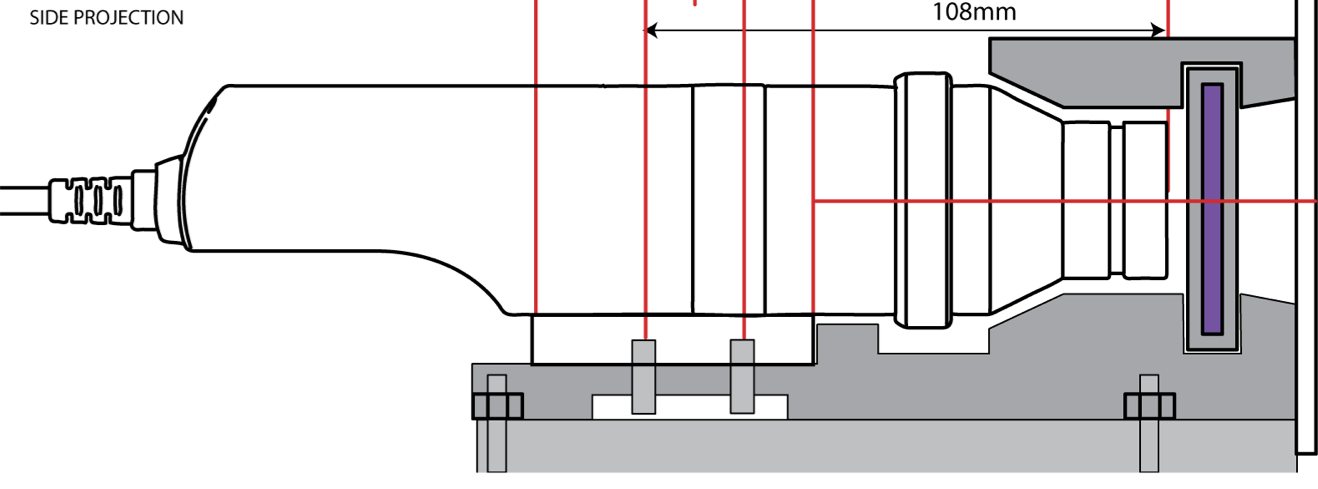
2.2.1. Focus The focus of the projected image is dependent on two main factors: the focus setting of the lens, and the projection distance. Assuming you have set the correct projection distance (confirmed using the Bosch DLR130), adjust the focus of the projected image by rotating the focus ring on the lens (outer barrel) until the projected image appears sharp and text is readable.
2.2.2. Size The size of the projected image is dependent on two main factors: the zoom of the lens, and the projection distance. Assuming you have set the correct projection distance, adjust the size of the projected image by rotating the zoom ring on the lens.
2.2.3. Aspect ratio For simplicity, the aspect ratio of the projected image should automatically match the aspect ratio of the display resolution (as set in the NVidia control panel). This way, the number of pixels per degree of visual angle will be the same in both vertical and horizontal directions, thus avoiding complications when calculating the dimensions, position, speed and acceleration of image elements in your experimental code. • Press the ‘Menu’ button, select ‘Aspect’ and press ‘Enter’. • Select ‘Auto’ and press ‘Enter’. This option automatically sets the aspect ratio according to the input signal.
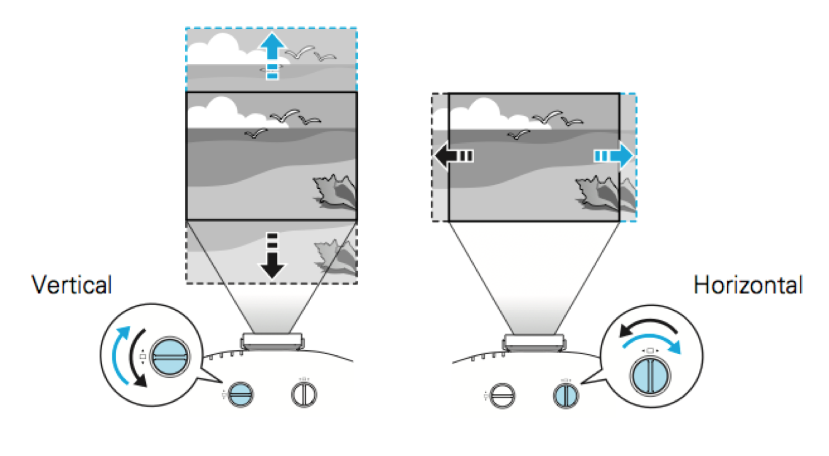
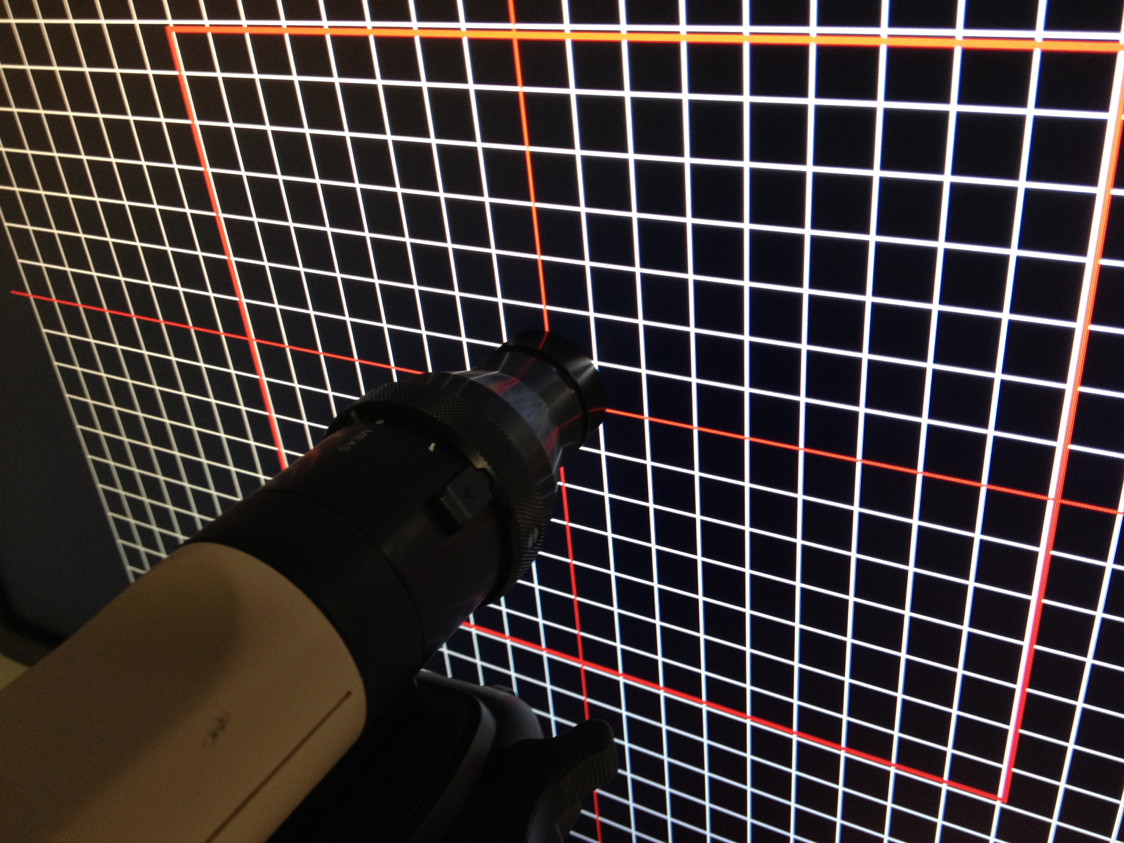
2.2.4. Position The two projected images from the Epson projectors should converge in the plane of the screen. Adjust the mirror(s) so that at least one of the projected images appears in the correct position on the calibration screen. • From MATLAB, call the function DisplayGrid.m. A white grid will be displayed on a black background, with a red crosshair at the center of each image. • First align the centers of the two images, since this is the most important part of the image in most experiments. Adjust the vertical alignment of the projectors using the screw on the back of the projector stand or the vertical lens shift dial on the top of the upper projector. • To adjust the horizontal alignment, use the horizontal lens shift dial on the top of the upper projector (the dial on the lower projector is unlikely to be accessible).
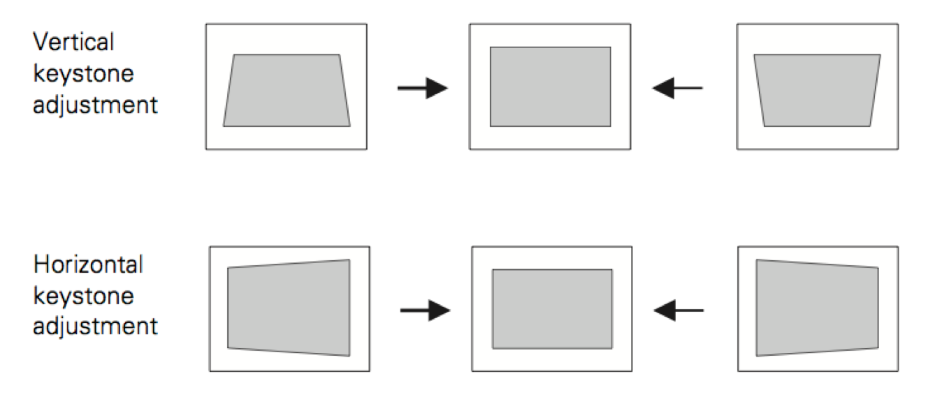
2.2.5. Image shape Since each projection is oriented at a slight angle away from the line orthogonal to the projection screen, a rectangular image will appear as an isosceles trapezium shape. This is called keystone distortion, and can be corrected as follows: • Press the ‘Menu’ button. Select the ‘Settings’ menu and press ‘Enter’. • Select ‘Keystone’ and press ‘Enter’. Select ‘H/V Keystone’ and press ‘Enter’ • Use the up and down arrow buttons to adjust the vertical keystone until the image appears rectangular and the grid lines appear parallel.
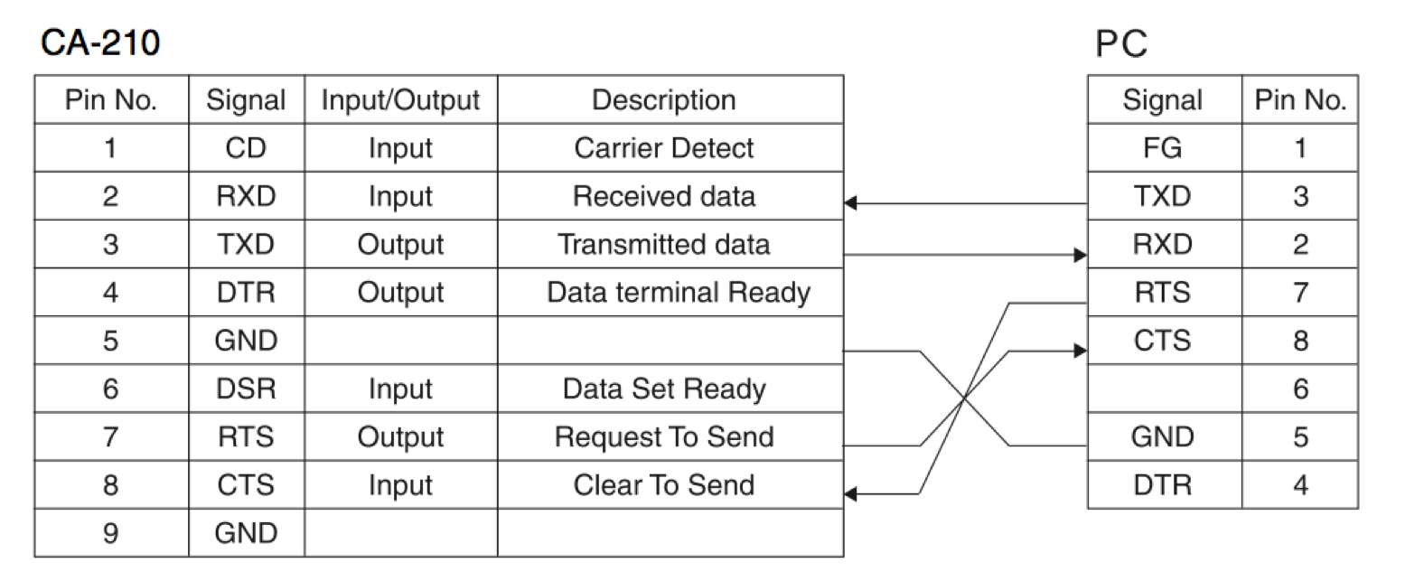
Luminance measurement will be performed via the Stereo_Stim workstation, located in the server room. Stereo_Stim has a DB-9 serial port installed via a PCIe board, and should appear in Windows Device Manager as ‘COM1’. Stereo_Stim’s serial port should be connected to the patch panel between the server room and magnet room using an RS-232 ‘null modem with full handshaking’ serial cable. This is different from a normal serial cable because it is wired in such a way that pins 2 & 3, 4 & 6, and 7 & 8 cross over between the two connectors. A second RS-232 serial cable with straight through wiring should be connected to the corresponding DB-9 connector in the magnet room, and the other end of that cable should be connected to the CA-210 serial output.
In order to perform luminance measurements, the projectors and calibration screen should be set up as described above, with the bore covers closed and both mirrors in place. Turn both projectors on for stereo calibration, and insert the first INFITEC filter into the slot between the photometer probe and the calibration screen (see diagram), making a note of which projector/eye the filter corresponds to.
To set up the Konica-Minolta CA-210 photometer:
- Make sure the power cable, probe cable and RS232 serial cable are plugged into the sockets on the back of the Konica-Minolta CA-210.
- Set the POWER switch to ON ( | ). The LCD display should read ‘Darken probe, push 0-cal key’.
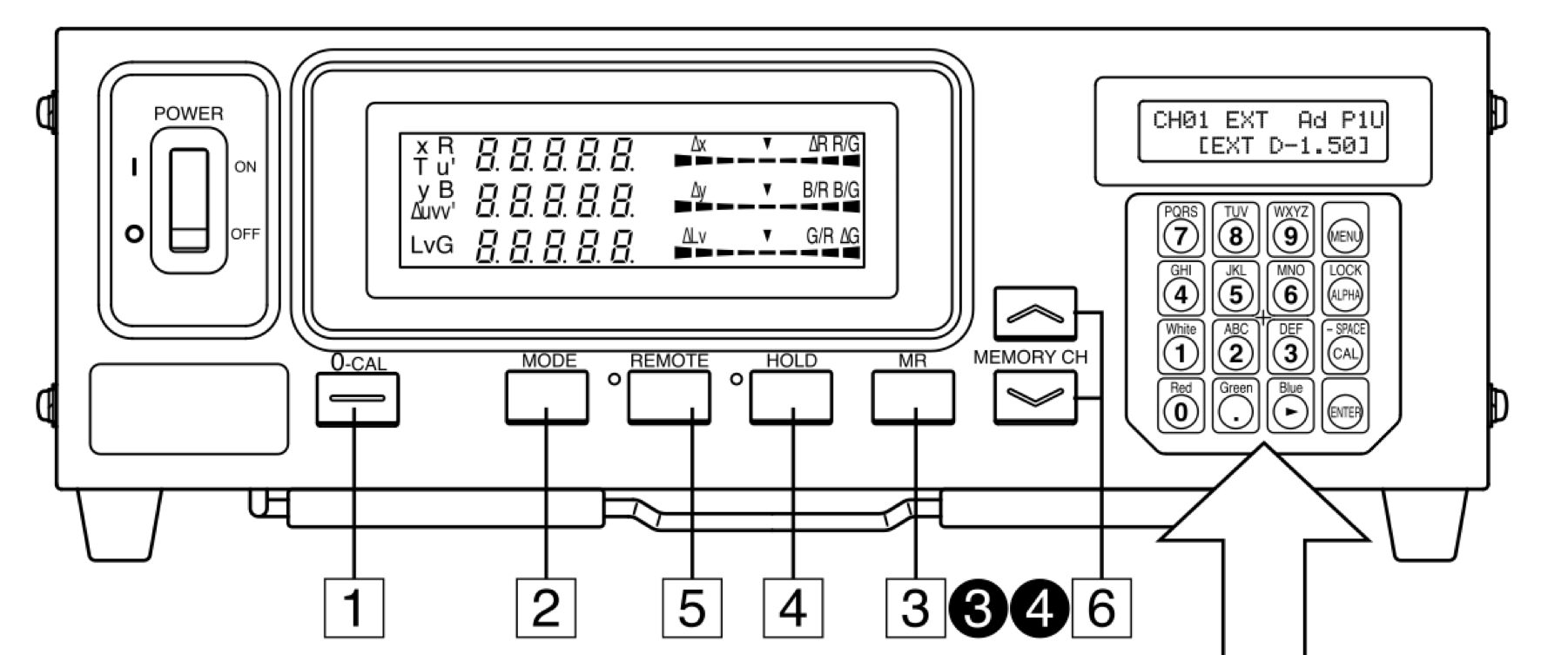
- Rotate the ring on the probe to ‘0-Cal’ and then press the ‘0-Cal’ button [1] on the front of the CA-210. The LCD display should now show a luminance measurement of 0 cd/m2.
- Return the ring on the probe to ‘Meas’. The LCD display should now show a luminance measurement greater than 0 cd/m2.
- Press the ‘Remote’ button [5]. The Remote LED will light, indicating that the CA-210 is awaiting serial port communication from the PC.
- Insert the correct INFITEC filter for the projector that you are currently calibrating into the slot in front of the measurement probe. The bottom projector uses the type A filter, which is used for the right eye and appears slightly reddish when you look through it. The top projector uses the type B filter, which is used for the left eye and appears slightly greenish when you look through it.
Since MATLAB is used for stimulus presentation in the NIF – via either PsychophysicsToolbox (Brainard, 1997;Pelli, 1997) or MonkeyLogic (Asaad et al., 2013) – it is convenient to use for luminance testing. In order to read data from the CA210 via the serial port connection, the Data Acquisition Toolbox must be available, which in turn requires a 32-bit version of MATLAB.
In the control room:
- Turn off the lights in the magnet room.
- Select the Stereo_Stim workstation and open MATLAB r2013b (or any version later than r2009).
- From the MATLAB command line, call the function ‘LuminanceCal.m’. A dialog box will appear asking you to enter the following information:
- Asaad, W.F., Santhanam, N., Mcclellan, S., and Freedman, D.J. (2013). High-performance execution of psychophysical tasks with complex visual stimuli in MATLAB. Journal of neurophysiology 109, 249.
- Ban, H., and Yamamoto, H. (2013). A non–device-specific approach to display characterization based on linear, nonlinear, and hybrid search algorithms. Journal of vision 13, 20.
- Brainard, D.H. (1997). The psychophysics toolbox. Spatial vision 10, 433-436.
- Jorke, H., and Fritz, M. (2003). Infitec-a new stereoscopic visualisation tool by wavelength multiplex imaging. Proceedings of Electronic Displays 2003.
- Pelli, D.G. (1997). The VideoToolbox software for visual psychophysics: Transforming numbers into movies. Spatial vision 10, 437-442.