Home - nichola7/ECE387Midterm GitHub Wiki
Welcome to the ECE387Midterm wiki!
I wanted to do a project that was interesting as well as something I had at the very least some interest in. I like video games so I thought the idea of trying to connect a video game controller to an arduino through bluetooth was challenging enough for this class and went in that direction. I had a roadmap for the project: Connect 5 LEDs, with each corresponding to each of the colors on the PS4 rockband guitar controller (green, red, yellow, blue, orange). Then I would attach a piezo speaker to the system that would emit a different frequency corresponding to each button. 5 buttons equal 5 frequencies. Then I would attach the HC-05 chip to the arduino, hopefully figure out a way to interface that with the guitar and arduino and then have the arduino make the correct LED and frequency play out of the speaker when the correct input was read by the HC-05 chip.
First the LEDs:
The code and diagram for getting the arduino to control an LED can be found here: https://www.arduino.cc/en/tutorial/blink
This code will make the LED blink, the part in the code that turned the LED off was edited out so the light stays on. My code for one LED follows:
void setup() {
pinMode(13, OUTPUT); }
void loop() {
digitalWrite(13, HIGH); }
As can be seen in the diagrams, the LED controlling is fairly straight forward.
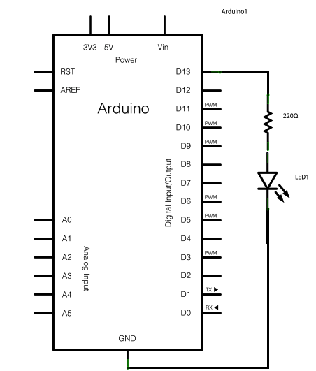 A 220 Ohm resistor needs to be connected in series to the LED to prevent the LED from burning out. The LED needs to have its short side connected to a digital pin that can be set to HIGH or LOW and the long side needs to be grounded. Because more than one LED is used, a breadboard is needed so that all the LEDs (and other devices) can be connected to ground.
 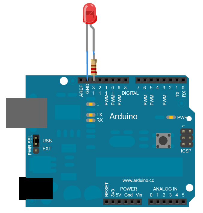 There were 4 of this type of LEDs that were connected. A green, red, yellow, and blue LED. There was no orange specific LED so an RGB LED needed to be connected. How to connect and use the RGB LED can be found here: https://howtomechatronics.com/tutorials/arduino/how-to-use-a-rgb-led-with-arduino/
Basically, the three pins corresponding to each of the three colors RGB need to be connected in series with a 220 ohm resistor than connected to a digital pin that can supply power. The fourth pin needs to be grounded. That schematic follows:
 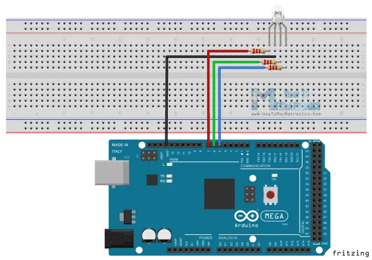 The individual code to get this RGB LED to emit an orange color follows:
int redPin= 7;
int greenPin = 6;
int bluePin = 5;
void setup(){
pinMode(redPin, OUTPUT);
pinMode(greenPin, OUTPUT);
pinMode(bluePin, OUTPUT);}
void loop() {
setColor(255, 0, 165);
}
void setColor(int redValue, int greenValue, int blueValue) {
analogWrite(redPin, redValue);
analogWrite(greenPin, greenValue);
analogWrite(bluePin, blueValue);
}
What is most interesting is that in my project, using the schematic and code from the links above, the green and blue LED values are switched. So in the set color Code the second number corresponds to blue and the third corresponds to green.
The Piezo Speaker:
The speaker connection is pretty straight forward, connect the correct end to ground the other side to power. That schematic follows:
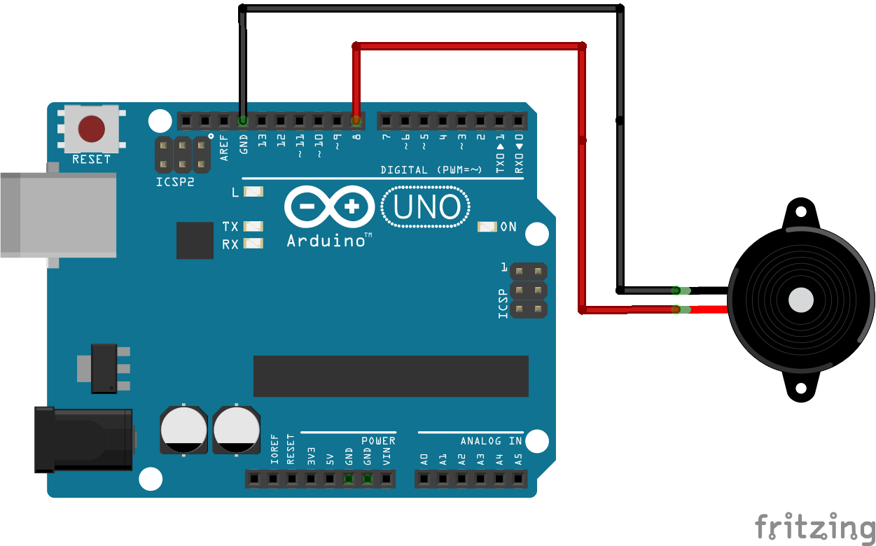
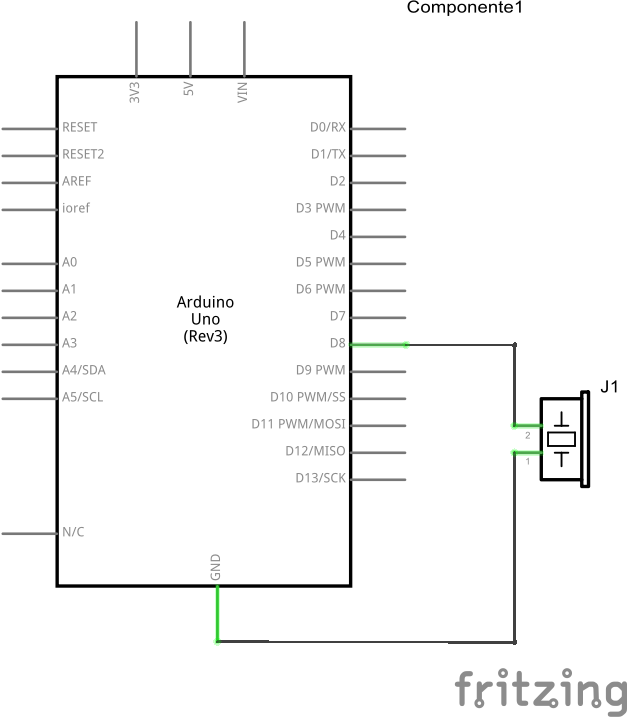 The tone melody was used and the schematics above are found here: https://www.arduino.cc/en/Tutorial/toneMelody
The speaker will play a tone using the tone function, basic code follows displaying the tone function and there are several variants of the that line of code throughout the program to create five different frequencies.
tone(8, 104, 1000);
The HC-05 Chip
The most challenging part of the project is the Bluetooth chip and its functionality with the arduino. The diagram below shows how to connect the chip and the code used to interface with the arduino follows:
http://exploreembedded.com/wiki/Setting_up_Bluetooth_HC-05_with_Arduino
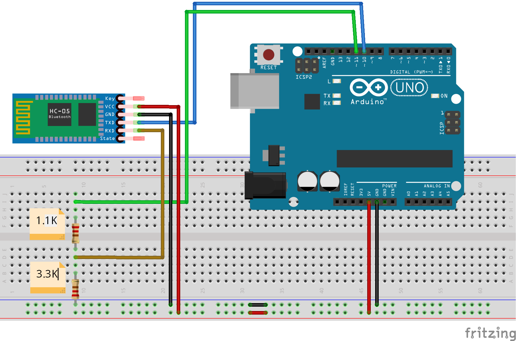 The biggest roadblock that could not be overcome was the ultimate connection of the controller to the chip. The chip was attempted to be moved to master mode and the controller connected but that failed. Ultimately, this is where the project ended. Unable to connect the controller the specific inputs that would control the separate LEDs and sounds could not be determined.