Loconet2Block V5 assembly - nh-finescale/ln2block GitHub Wiki
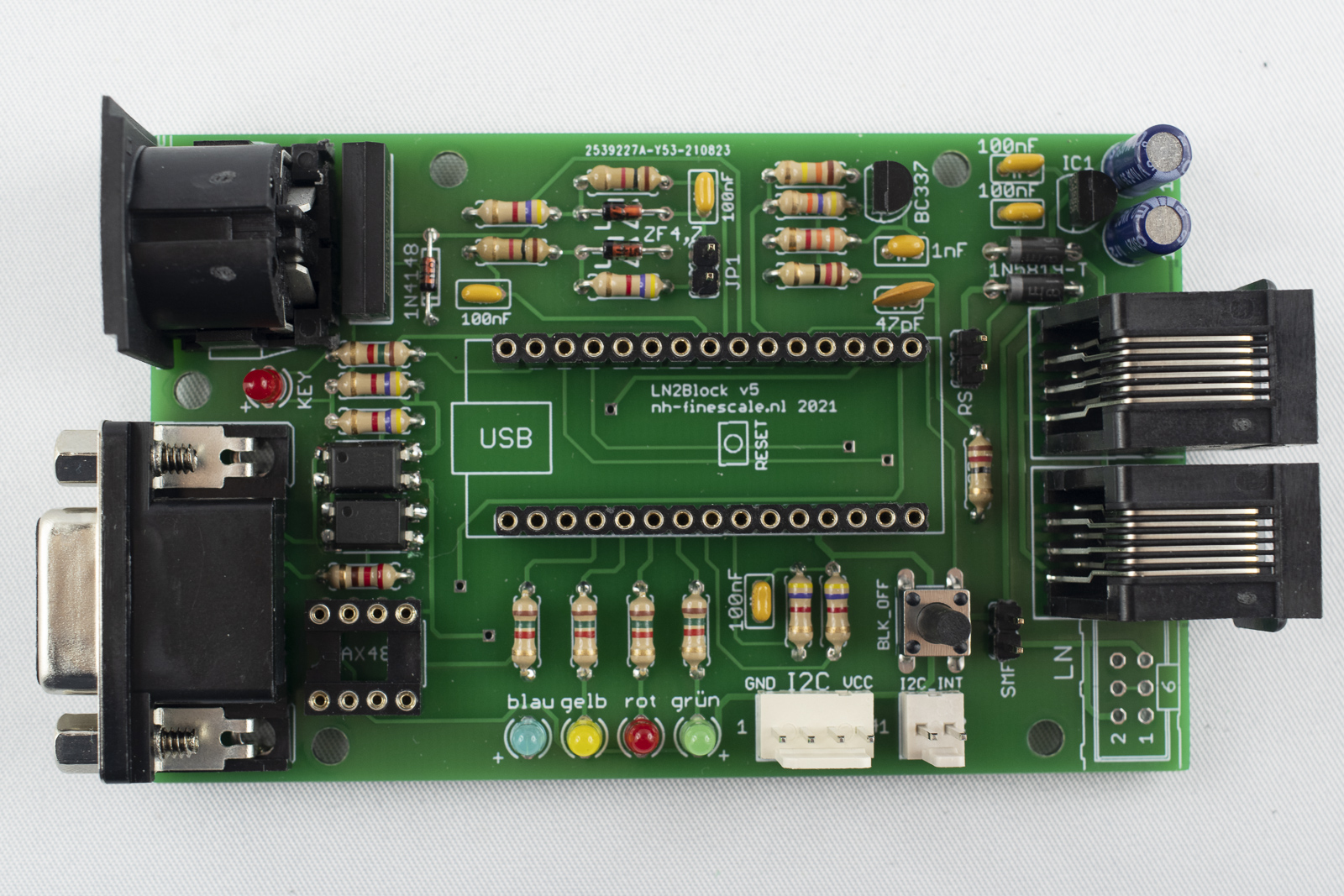
Board assembly
-
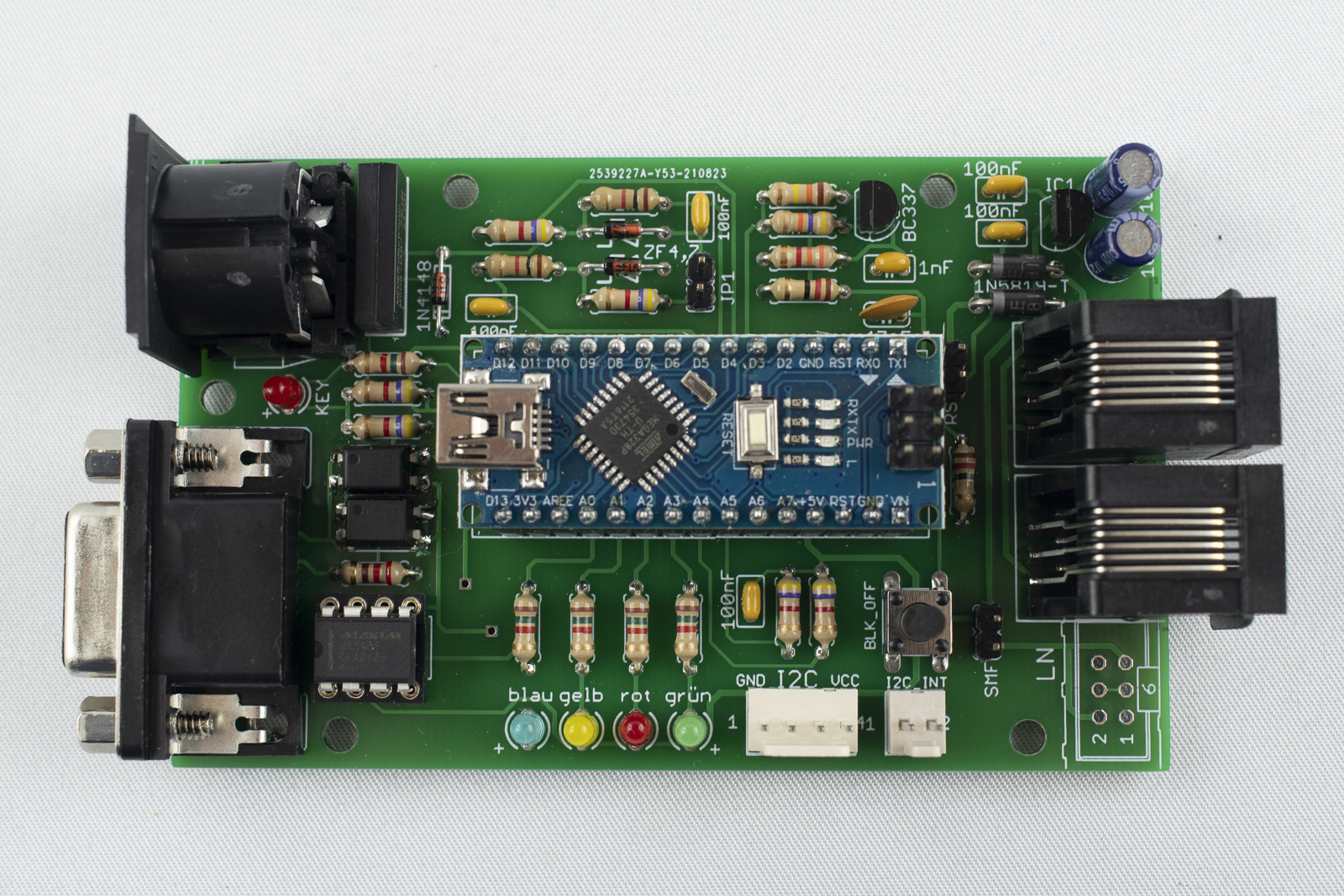
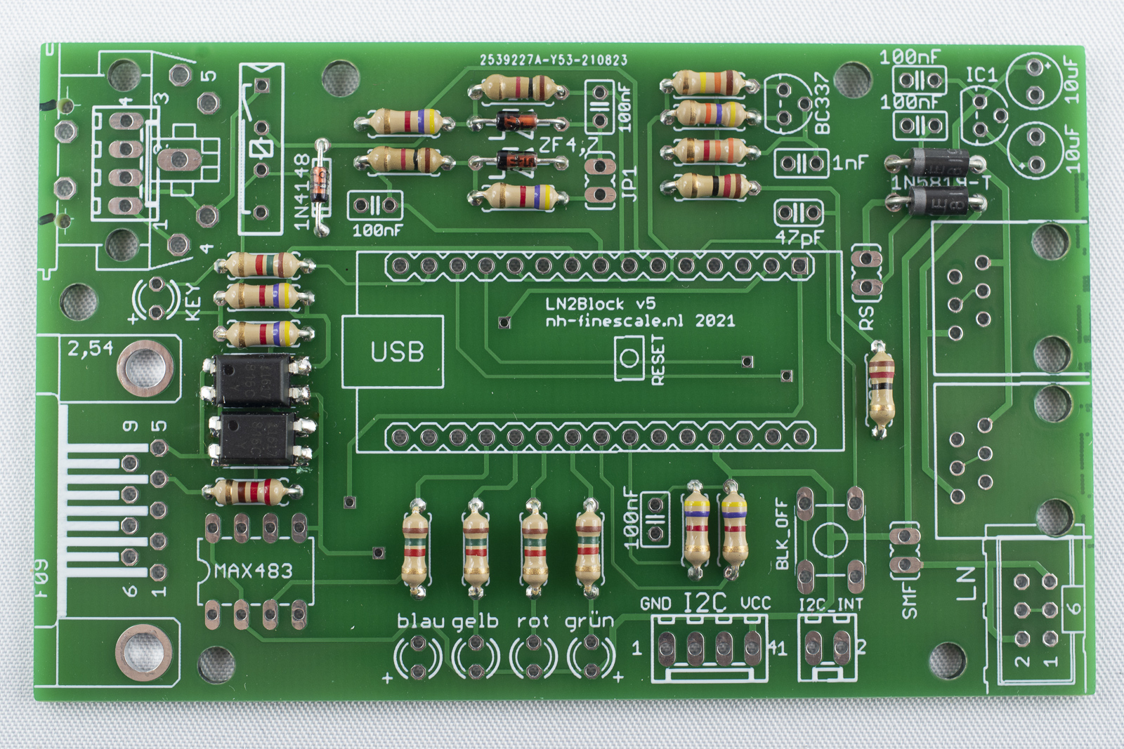
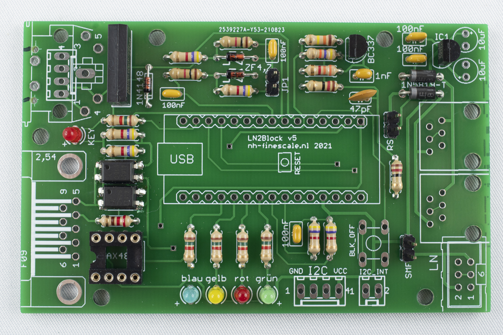
For the assembly of the board it is a good practice to first solder the lowest components and then move to the higher ones. This makes it easier to keep the components in place.
-
After having inserted the components into the holes of the board, bent the wires on the backside a little bit to the outside. This prevents the components from falling out, when turning the board for soldering. Do not bent to much!
-
Place some components and solder them afterwards. Do not place to many components before soldering as the wires might become obstructive for soldering.
-
Cut the wires after soldering a little bit above the solder point.
Solder the Optocouplers
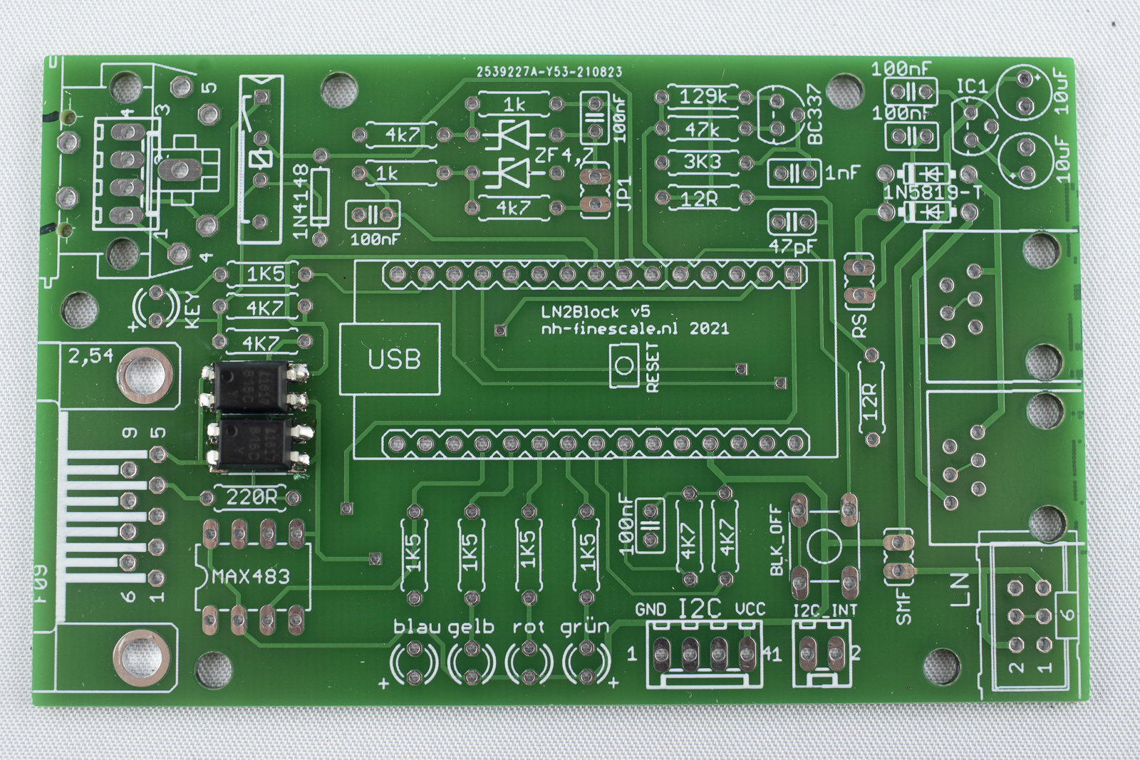
- First, tin all the pads for the two optocouplers (4 pads each)
-
Place an optocoupler on the pads by the help of a pair of tweezers. Align the small notch on top to the outside of the board.
-
Solder on pin of the optocoupler. Note the device sinks down to the board when the tin gets fluid.
-
Make sure that all pins are still properly aligned on the pads. Correct if necessary!
-
Solder the remaining pins.
-
Repeat for the second optocoupler. Orientation of the notch is the same, towards the outside of the board.
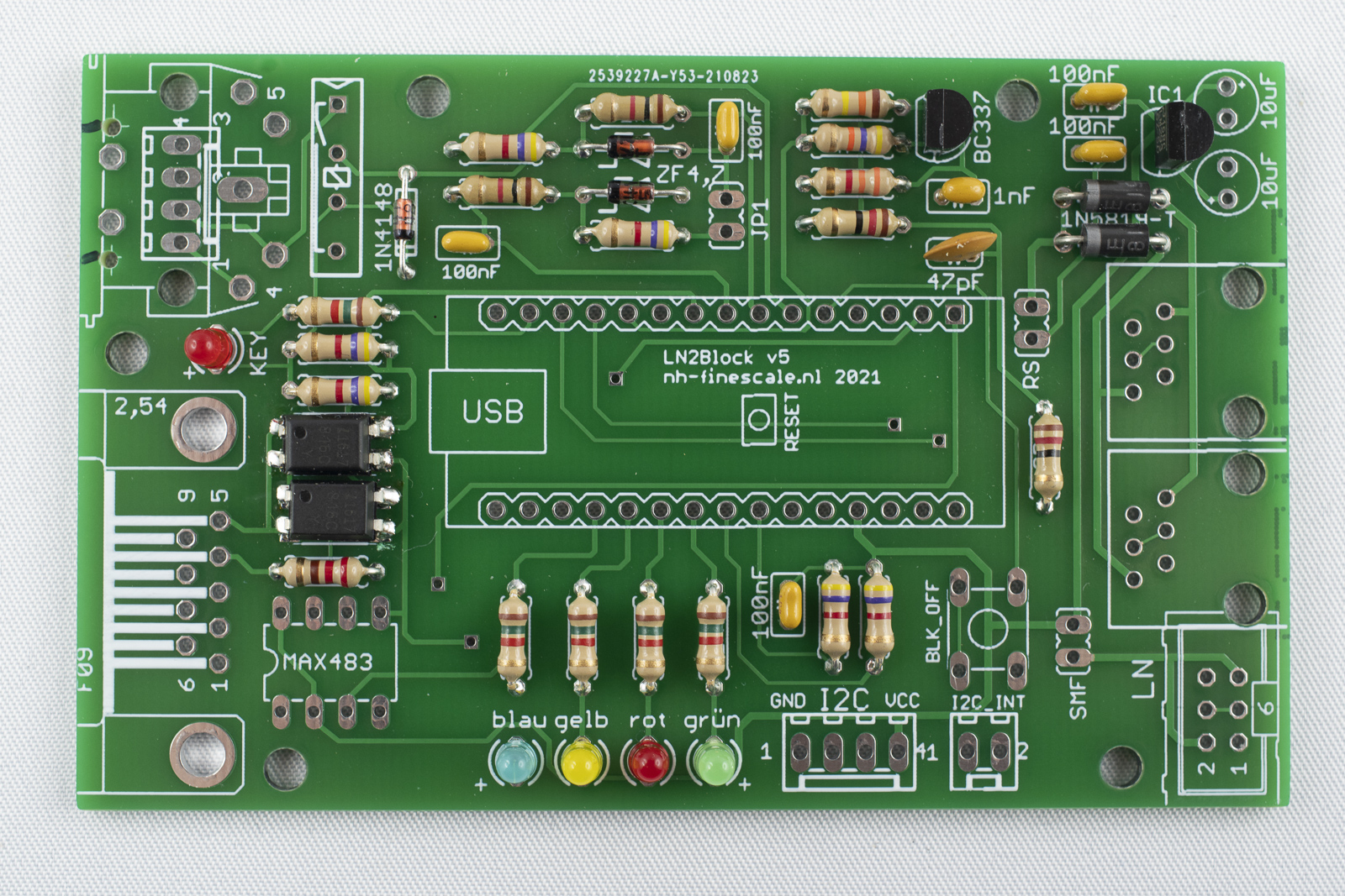
Solder the diodes
-
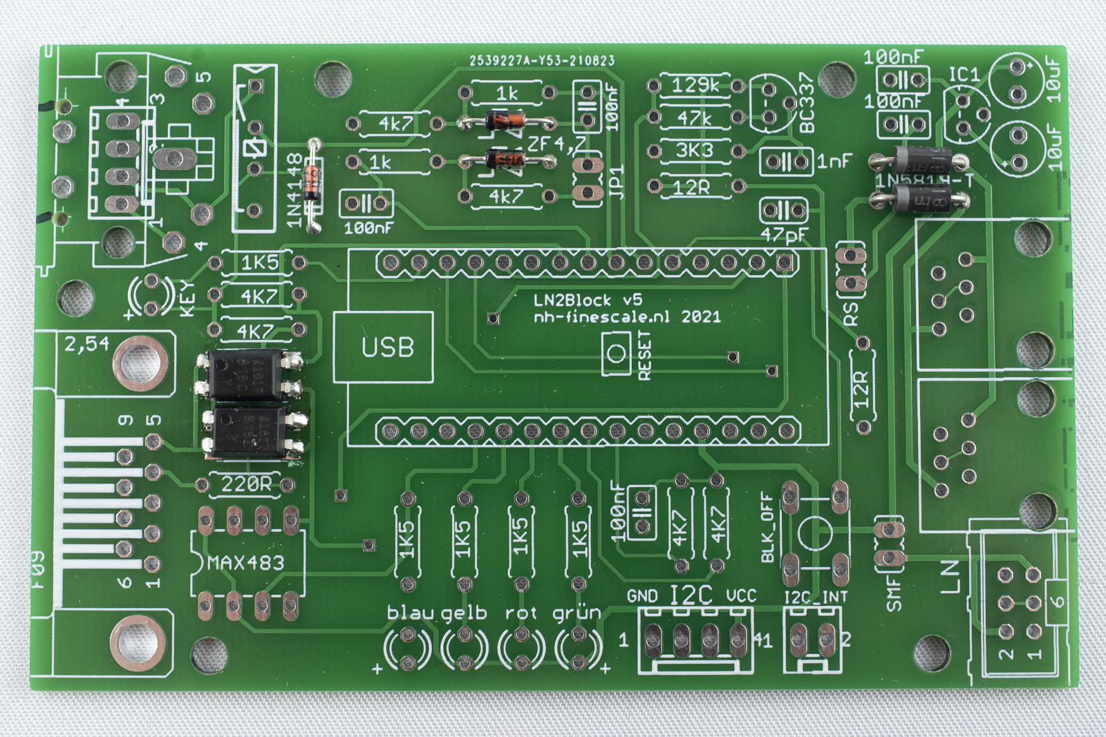
Solder one diode 1N4148 top left. Black ring towards the inside of the board.
-
Solder two diodes ZF 4,7 top center. Black ring to the left.
-
Solder two diode 1N5819 top right. Grey ring to the left.
-
Cut the wires.
Solder the resistors
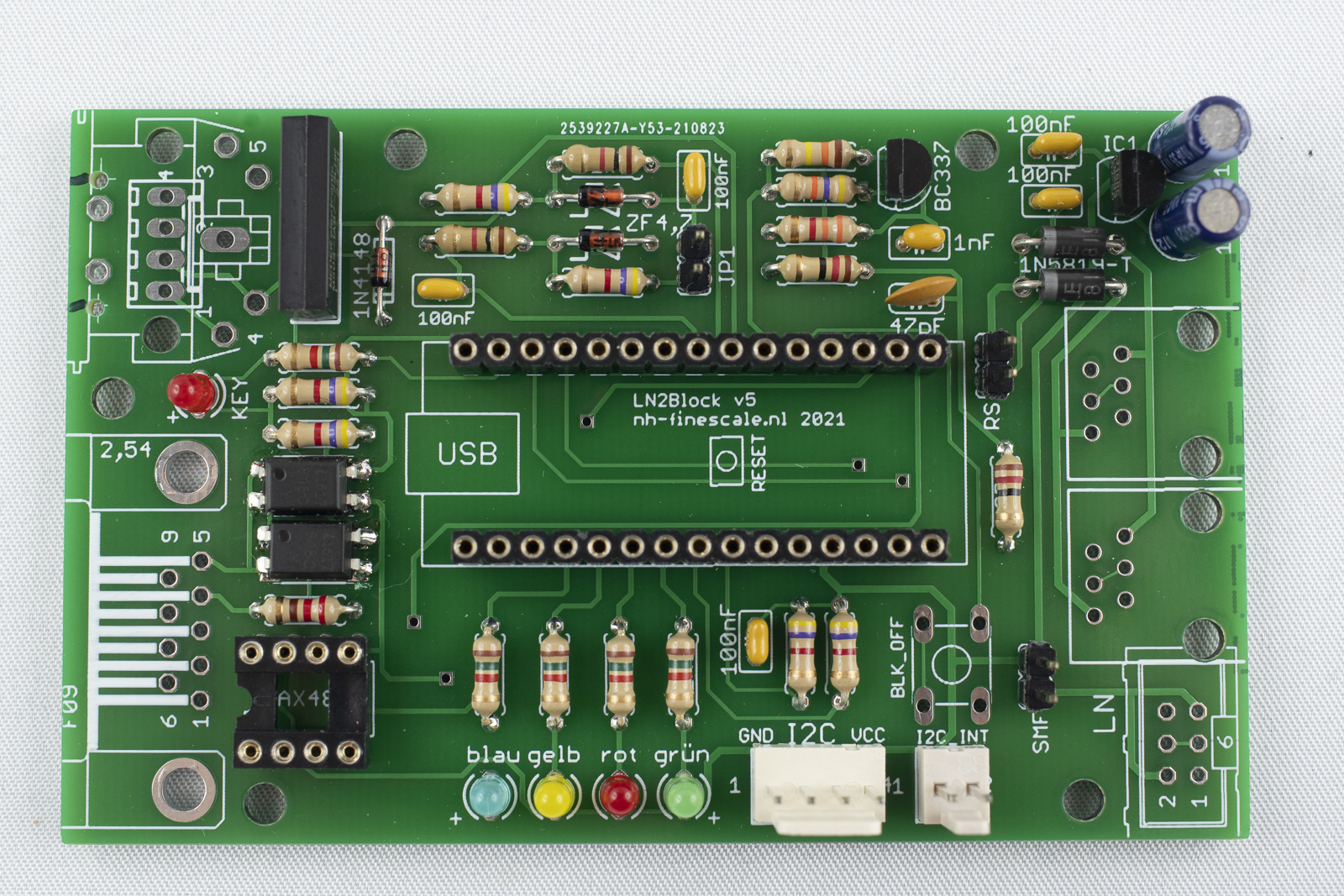
Solder the resistors to the marked positions. Orientation does not count. Bend the wires of the resistors directly at the package, otherwise they will not fit in the holes.
Solder the capacitors
-
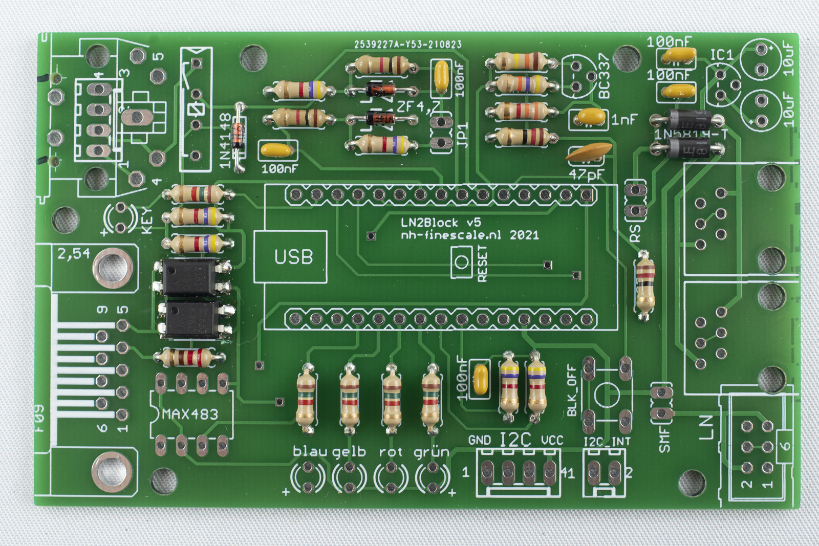
Solder the ceramic capacitors (5x 100nF, 1x 1nF, 1x 47pF). Orientation does not count.
-
Cut the wires afterwards.
Solder the transistor and the voltage regulator
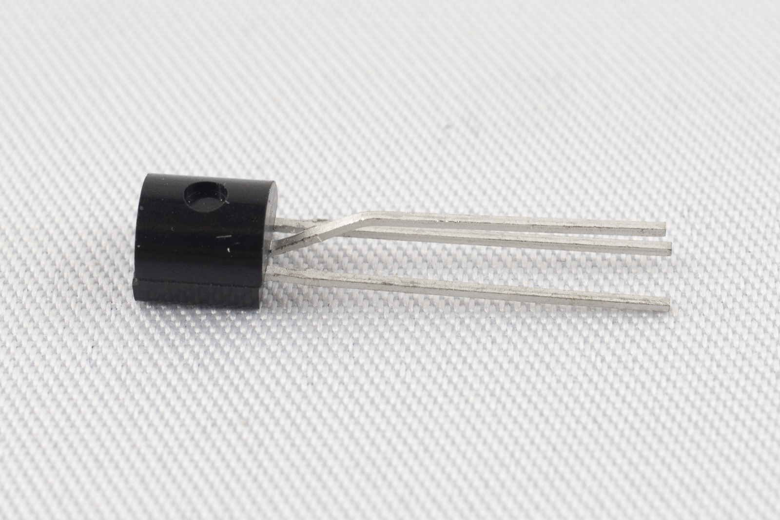
- Next, solder the transistor BC337, top center. To do so, bent the middle pin forward and then, one millimeter away down again so that the three pins form a triangle.
-
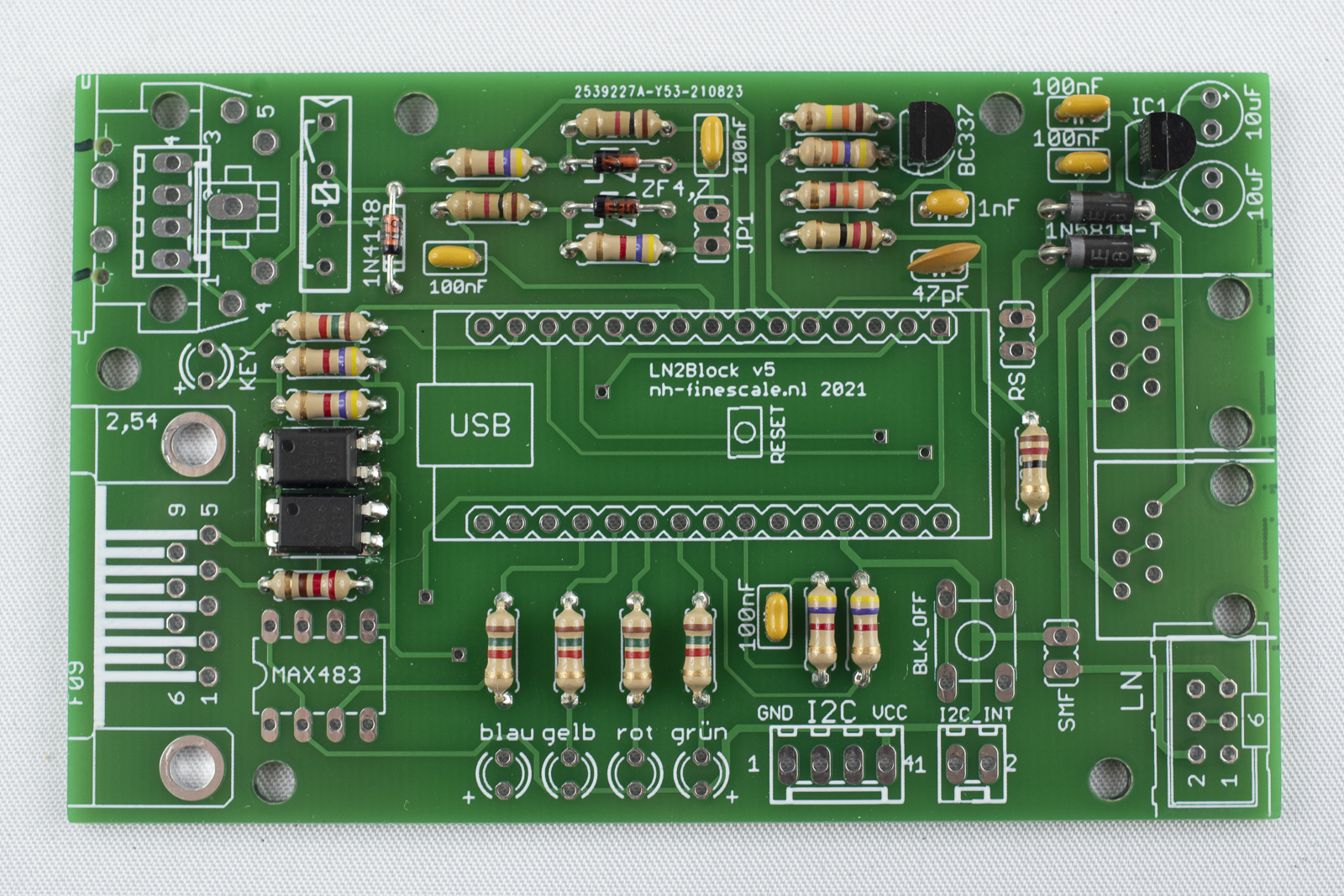
Insert the transistor into the board (flat side to the left) and solder it.
-
Repeat for the voltage regulator LM2936Z-5.0, top right. Bend the pins as described above, insert it into the board (flat side left) and solder.
-
Cut the wires.
Solder the LEDs
The LEDs have to be oriented correctly. The two pins have different length. The longer pin is "+", the shorter pin is "-". On the board, the "+" pins are marked.
-
Insert a red LED at the position marked "key". The long pin is aligned towards the bottom. First solder one pin and make sure that the LED is oriented straight. If necessary, heated up the solder point and move the diode to the correct position with one finger while still heating the solder point. If the position is correct, remove the solder iron and the release the finger. Solder the second pin.
-
Solder a blue, yellow, red and green LED (from left to right) at the bottom. The long pin has to be oriented towards the outside of the board. Solder only on the of each LED and correct the orientation as described above, if necessary. If everything is fine, solder the seconds pins and cut the wires afterwards.
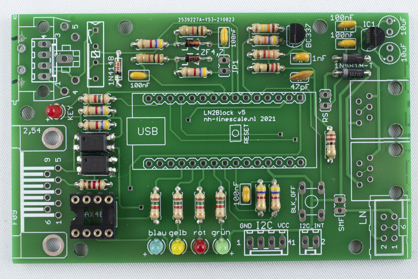
Solder the IC socket
Next, solder the IC socket bottom left. The notch in the socket should point to the outside. To make sure that the socket is flat on the board first only solder on pin of the socket and check the alignment. When the position is fine, solder the remaining pins.
Solder the reed relay
- The reed relay is positioned top left. It should be positioned in that way, that the writing can be read from the center of the board.
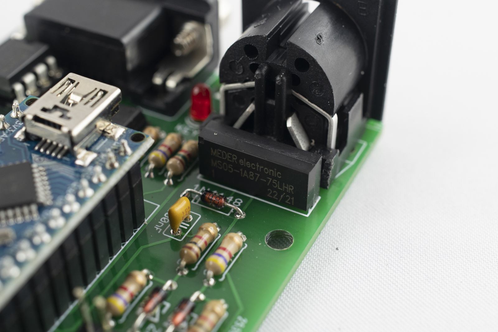
- Like for the IC socket, first solder one pin and make sure that the relay is sitting flat on the board. Then solder the remaining pins.
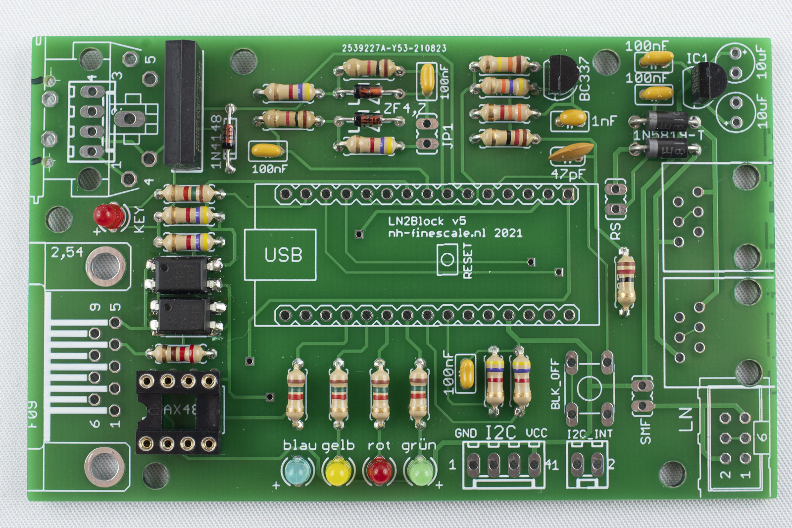
Solder the 2x pin headers
Next, solder the 2x pin headers on the board. Again, first solder only one of the two pins and check the alignment. Correct if necessary and the solder the second pin.
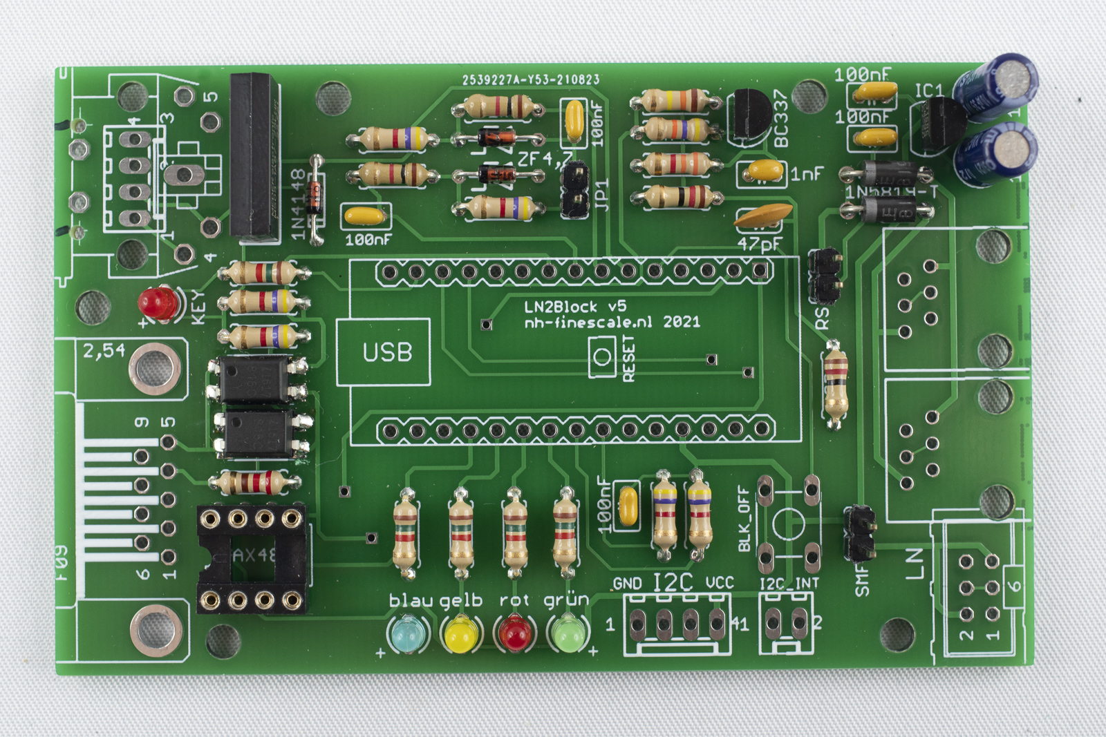
Solder the electrolytic capacitor
Solder the two electrolytic capacitors top right. The orientation if important! The capacitors are marked with "-" on the housing near on of the legs. In addition, one of the legs is shorter then the other one. The shorter leg is "-" the longer leg is "+".
On the board, "+" is marked in the print. Orient the capacitors in the way that "-" is facing to the other capacitor.
Solder the headers for the Arduino
- Next the female headers for the Arduino should be soldered. In order to proper align them it is a good practice to place them on the already soldered male headers of the Arduino.
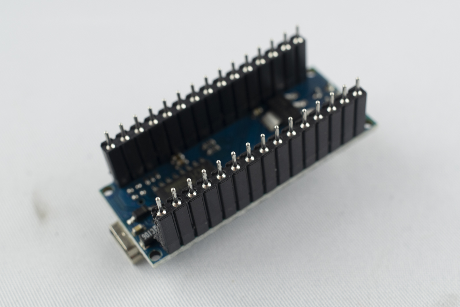
- Then, insert this package in the board and only solder two distant pins. Make sure, that the headers are positioned flat on the board and correct if necessary. I every thing is in place, solder the remaining pins and remove the Arduino after soldering the headers.
Solder the connectors for I2C
-
On the bottom of the board, next to the LEDs, there is a 4x and a 2x connector for I2C. Insert them with the clip facing towards the outside of the board.
-
Solder on single pin first and check the proper alignment. Correct if necessary and then solder the remaining pins.
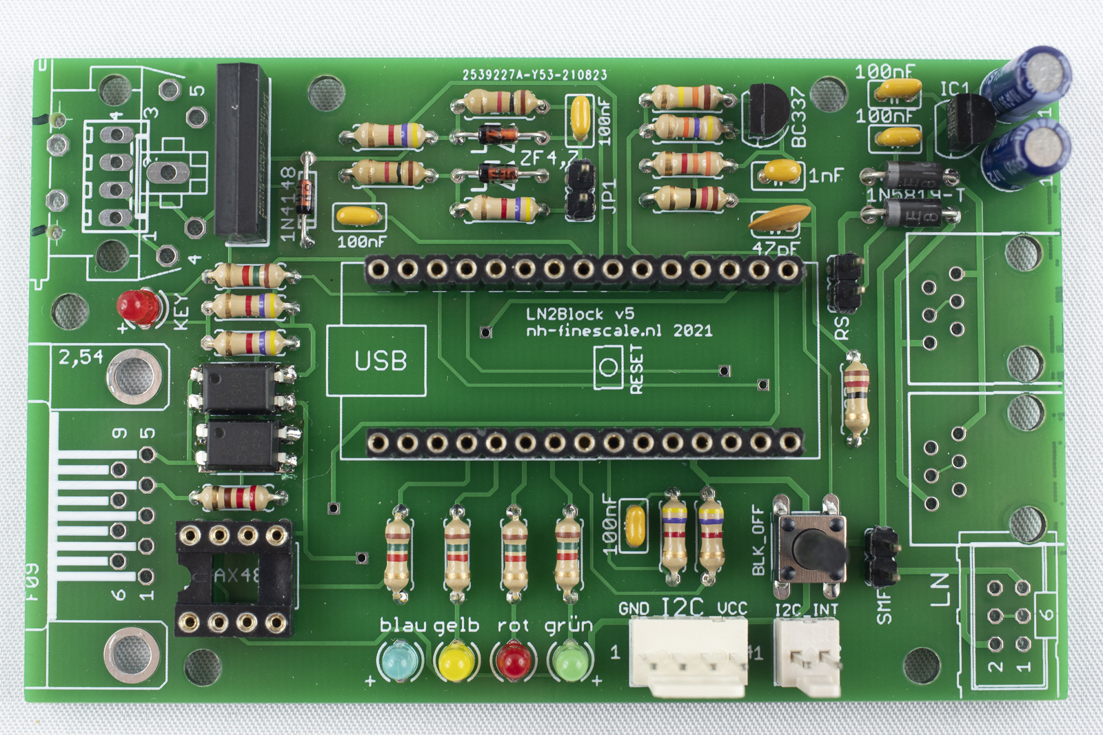
Solder the push button
-
Place the push button in the four holes next to the I2C header. The pins should be aligned in the same orientation as the pads. If rotated by 90 degrees they will not fit.
-
Make sure that the push button sits flush on the board and then solder the four pins.
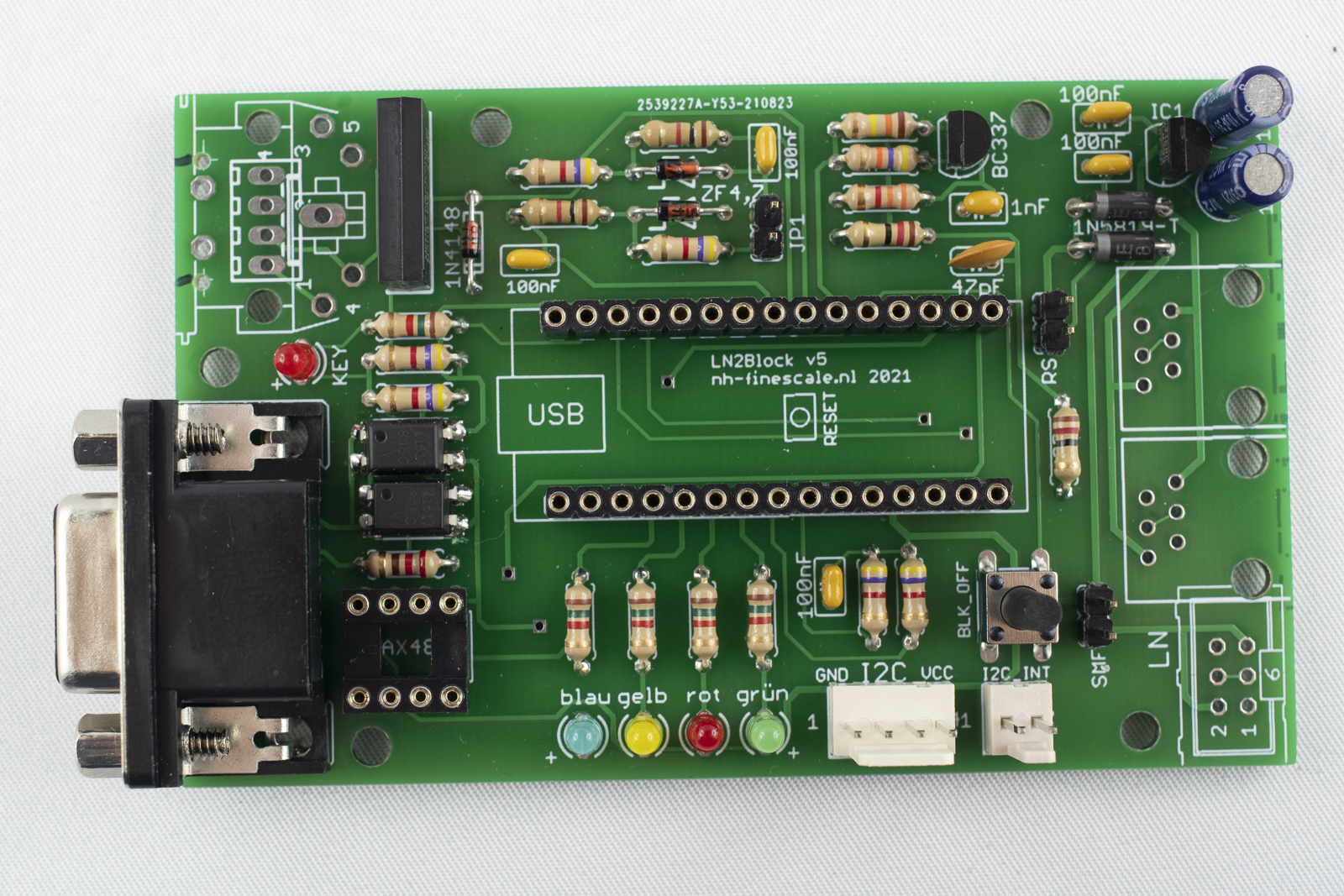
Solder the 9 pin D-Sub connector
-
Next solder the 9 pin D-Sub connector at the left of the board. The clamps at the outside should fit into the big holes. Solder the pins of the connector.
-
Do not forget to also solder the clamps to the holes. It is not necessary to fill the complete holes with tin!
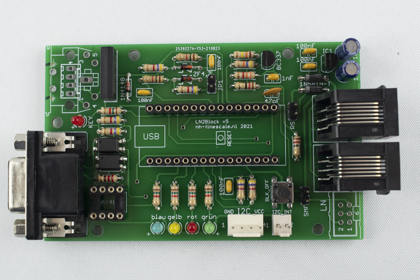
Solder the RJ12 connectors
If you want to connect LN2Block using normal LocoNet cables, now solder in the two RJ12 connectors. If you prefer the SMF connections solder the 6 pin connector bottom right instead. Both connections together are not possible.
-
Before the RJ12 connectors (LN-connectors can be soldered on the board, the ridge at the side facing to each other has to be removed. Otherwise they will not fit in place! Use a sharp knife to cut them away or use a file instead. The ridges at the outside can stay in place.
-
Insert the connectors in their position and solder them.
Solder the 5pin DIN socket
-
Put the 5pin DIN socket in place and solder on pin.
-
Make sure that the socket is place flush on the board and solder the remaining pins.
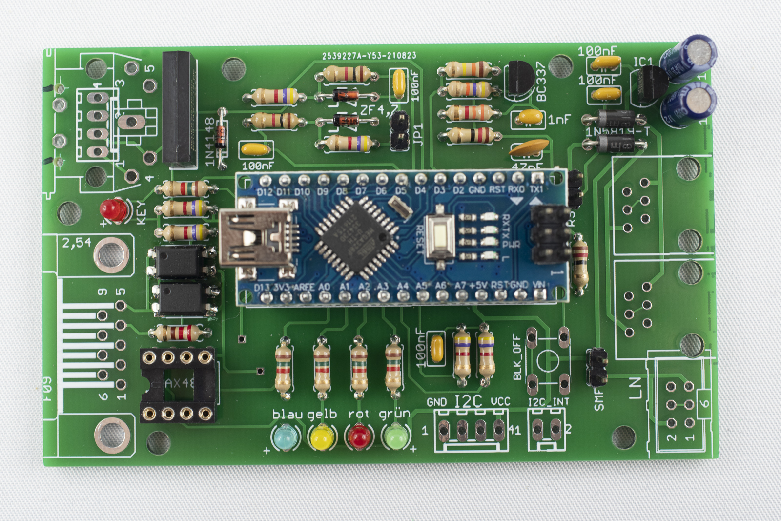
Insert Arduino the IC
-
Insert the IC in the socket at bottom left. The notch has to be facing towards the D-Sub connector. Make sure that all pins are inserted into the socket! It helps to bent the pins a little bit to the inside on a straight surface.
-
Place the Arduino into the headers. The USB-socket has to point towards the left. Dependent on the USB-cable available it is a good idea to first program the Arduino before inserting it into the board as the connector might not fit then.