HW5 - ndm736/ME433_2020 GitHub Wiki
To add a little color to our display we'll use some WS2812B addressable color LEDs in an 8mm package from Sparkfun. The WS2812B is also called a Neopixel and comes on sticks, rings, matrices, and infinitely long lengths of flexible tape.
Traditional color LEDs are very pin intensive. Each LED is really a red, green, and blue LED cast inside the same plastic lens. Each needs to be set for intensity using a unique PWM, and a microcontroller like the PIC32MX170F256B has only 5 PWM pins, so it couldn't even drive 2 LEDs! Other brands of microcontrollers have many more PWM capable pins, but even then it would take a lot of multiplexing to drive a lot of color LEDs.
WS2812B are a nice solution. They have a built-in controller that takes a single digital signal to set the brightness of the red, green, and blue LEDs, and if you immediately send another color, the data is passed-through to the next WS2812B. That means you can chain WS2812Bs in series and control each color and brightness uniquely with only one pin from the microcontroller!
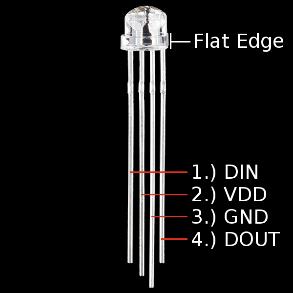
The datasheet does not do a good job of identifying the pins on the 8mm version (or identifying many other specs), but here is a photo that shows that the LED has a flat edge and starting on the flat edge and working in, the pins are data-out, GND, Vdd, data-in. WS2812B run on 5V, so connect Vdd to 5V from VBUS on the USB breakout. There is no reverse voltage protection on the WS2812B, so if you plug it in backwards, you will damage the LED. It will get extremely hot, and possibly pop when the plastic lens melts on the inside faster than the outside, so be very careful! Wire up 4 WS2812B, with the first connected to a digital pin from the PIC (I used B6), and data-out of the first chip to data-in of the second chip, and so on. Put a 1uF or 0.1uF from Vdd to GND on every other WS2812B.
It takes 24 bits to set the color of a WS2812B, 8 bits for each of the red, green, and blue LEDs, MSB first. The weird thing about the communication is that, because it is asynchronous and doesn't use a clock, the timing is very important, and every bit contains both a high voltage and a low voltage. A logic One bit is high for 1.36uS and low for 0.35uS, and a logic Zero is high for 0.35uS and low for 1.36uS, each deviating by no more than 0.15uS. If there is ever more than 50uS of low, the pass-through starts over (so this is the reset time).
Once you set the color of a WS2812B it stays that color until you give it a new color. When the chips first power on they are bright blue, so as soon as you power them you probably need to turn them all off.
The PIC does not have a peripheral like UART or I2C that can control the WS2812B (I have seen some references to hacking SPI to make it work). We will "bit-bang" the protocol to control the colors. This means a very manual method of turning a pin on, delaying, turning the pin off, delaying, etc. This is annoying because it will take a lot of CPU time, but they are inexpensive and colorful, so we'll do it.
There are lots of ways to manage the pin timing, using the core timer or the fact that each system clock cycle is a set amount of time and Nop()ing to do the delay. We will use Timer2 to make the delays, and a preallocated array to store the values of the bits. There is not enough time in between sending the bits to calculate what the next bit is, so we will convert the desired colors into an array of bits, then loop through the array every time we update the colors.
Take a look at the ws2812b sample code, which is half complete, with comments that describe what you need to finish. The h file contains a structure to link the red, green, and blue together, which will make it easier to pass color variables between functions. The c file contains ws2812b_setup(), where you need to initialize Timer2 to be 48MHz, and initialize the pin you want to use.
ws2812b_setColor() is the main function. The function takes as input an array of colors and the number of WS2812Bs in the circuit. In the function, you need to loop through each pixel in each color, and into another array, save the time in Timer2 ticks at which the pin should invert to blink out the highs and lows to make the logic Ones and Zeros. Once this array is made, it is a simple process to set Timer2 to start at 0, and inside a loop wait for the timer value to hit each array value, and when it does invert the pin. The while loop adds some extra cycles, which could knock the timing off, so the LOWTIME and HIGHTIME constants are adjustable. The hard part here is that the nScope is not quite fast enough to see the bits at full speed. To debug, I made all the delays 10x longer, to check if my bits matched my color bits, and then went back to full speed to see if the WS2812B output the right color.
Once you can set the colors, use the HSBtoRGB() function to generate a changing array rainbow of colors to display on your LEDs.
Upload your code in a folder called HW5, and make a demonstration video to upload to Canvas.