Tutorial How to generate TSX files - nataliapc/makeTSX GitHub Wiki
Tutorial: How to generate TSX files
by Natalia Pujol (@NataliaPC @ishwin74)
2018.11.16 : 1st version
2019.02.09 : 2nd version
INDEX
- Basic technical concepts of tape data encoding
1.1. Bits encoding
1.2. Bytes encoding
1.3. Data blocks
1.3.1. Header blocks
1.3.2. Data content blocks
1.4. The new #4B block - The makeTSX program
- Steps to create a good conversion to TSX
3.1. Digitize the tape to WAV format
3.2. Using the makeTSX program
3.3. Error control
3.4. Manual signal restoration
3.5. Data verification
3.5.1. Verification of tapes with MSX blocks
3.5.2. Verification of tapes with Spectrum blocks
1. Basic technical concepts of tape data encoding
Most of the old 8-bit computers hare using FSK (Frequency-shift keying) to storing data on magnetic media. This method is based on changing the frequency of the signal to define two or more symbols to store. More specifically, in the case at hand, there would be two: zeros and ones.
Each system used its own coding system: different frequencies, pulse repetitions, parity systems and control bits. Here we will see the ones used by the MSX computers.
1.1. Bits encoding
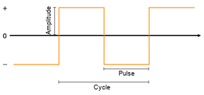
To encode bits (zeros and ones), we use pulses. A pulse is a state of the signal (low or high), and two pulses create a cycle, after which the initial signal state is obtained again.
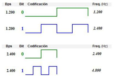
As we can see in the following image, to encode a bit 0 we use 2 pulses while for a bit 1 we use 4, being its duration the same due to their different frequency. This is true in the MSX system, unlike the Spectrum or SVI-318/328 encoding, in which a bit 0 and a bit 1 don't have the same length.
1.2. Bytes encoding
The MSX standard uses LSB (Least Significant Bit) convention to encoding bytes, which consists in showing bits from the least significant bit to the most significant bit, unlike Spectrum that uses MSB (Most Significant Bit) that reverses the order of appearance.
In addition to LSB, there is several control bits surrounding the bytes called start bits and stop bits. In this case a single start bit to 0 and two stop bits to 1 are used. So, to encode a byte, we would have 11 bits in the following way:
| 1 Start bits | Byte (8 bits in LSB order) | 2 Stop bits |
|---|---|---|
0 |
b0 b1 b2 b3 b4 b5 b6 b7 |
1 1 |
Example for encoding a byte with value 40:
0 0 0 0 1 0 1 0 0 1 1
This type of coding comes within KCS (Kansas City Standard) which is the one adopted by the MSX system for tape recordings. There are several forms of KCS coding incompatible with each other, for example those of the following systems: MSX, ABC 80, Acorn BBC/Electron, MicroBee, Dragon/CoCo, SVI-3x8, ...
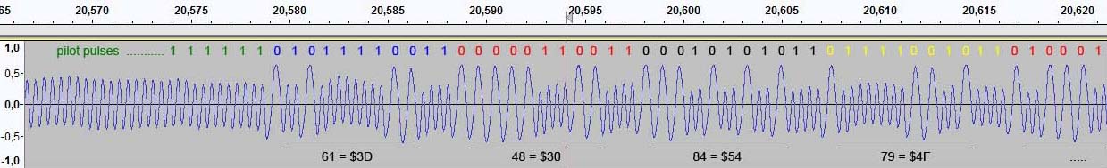
images/bit_bytes_example.jpg MSX bit/byte decodification example from rounded pulses.
1.3. Data blocks
The bytes are grouped into data blocks separated by silences. These blocks consist in series of pilot pulses that indicate to the computer the baudrate used, and then the block bytes.
In MSX there are two types of pilot pulses: long (for the header blocks) and short (for the data content blocks). Both are encoded like they were a series of consecutive bits 1 (using bit1 frequency), but they differ in the number of pulses that contains.
The following table has information about the different pilot pulses:
| Bauds | Pilot pulses type | Pulse frequency | No. pulses | Length |
|---|---|---|---|---|
| 1200 | Long | 2400 | 30720 | ~6.1 sec |
| 1200 | Short | 2400 | 7680 | ~1.5 sec. |
| 2400 | Long | 4800 | 63488 | ~6.3 sec |
| 2400 | Short | 4800 | 15872 | ~1.6 sec |
On the other hand, there are 3 standard types of data blocks: BINARY, ASCII and BASIC. They are differentiated by an ID byte repeated 10 times in its header blocks and by the data structure of its data content blocks as we will see below.
1.3.1. Header blocks
Content of a header block:
| Offset | Description | Values |
|---|---|---|
| - - - | Long pilot pulses | See table above for the no. of pulses |
| 0x00‑0x09 | 10 bytes ID telling us the type of data content block that will come next | BINARY (0xD0), ASCII (0xEA), BASIC (0xD3) |
| 0x0A‑0x0F | 6 bytes with the block name | The name that will appear in the "Found:" |
1.3.2. Data content blocks
All data content blocks start with a short pilot pulses followed by the data itself.
The BINARY type have 6 bytes at the beginning indicating the start (2), end (2) and execution (2) addresses of the block in RAM. Following is the byte data.
The ASCII blocks contain a BASIC program in ASCII format that are divided in subblocks of 256 bytes length. Each subblock has its own short pulse pilots and are separated by silences. The last subblock is filled with 0x1A until it reaches 256 bytes length.
And the BASIC blocks contain a tokenized BASIC program followed by 7 bytes 0x00 indicating the end of the file.
1.4. The new #4B block
In TSX files a new block type is added to the TZX 1.20 specification. Because of this the TSX files are also defined as TZX 1.21 at file header.
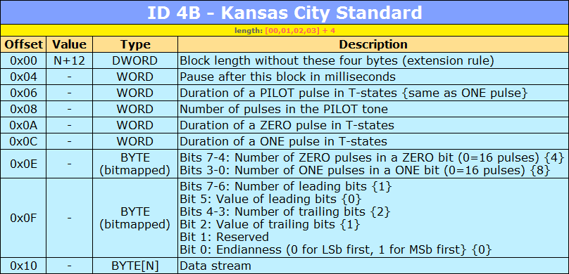
This new block with ID #4B and created by @Blackhole, allows coding blocks of data that follow the KCS standard, so data from all the systems that adopted it can be included.
images/ID4B_KansasCityStandard.png
For the specific case of the MSX, the configuration of a block #4B for a header block at 1200 baud would be this way:
| Offset | Description | Values |
|---|---|---|
| 0x06 | Duration of Pilot pulse | 729 T-States |
| 0x08 | No. Pilot pulses | 30720 pulses |
| 0x0A | Duration of a ZERO pulse | 1458 T-States |
| 0x0C | Duration of a ONE pulse | 729 T-States |
| 0x0E | BIT Configuration | 0x24 (00100100b):0010 = 2 pulses for a ZERO0100 = 4 pulses for a ONE |
| 0x0F | BYTE Configuration | 0x54 (01010100b):01 = 1 start bit0 = Start bits are ZERO10 = 2 stop bits1 = Stop bits are ONE0 = Reserved0 = LSB bits order |
2. The makeTSX program
Once the TSX format was defined with the new block #4B, we had to start creating TSX files, but despite having all the tools of the TZX, we needed a tool that was able to extract specific MSX #4B blocks from a WAV and generate the TSX with them. And so makeTSX was born.
This program is very similar to WAV2CAS or MAKETZX, since it allows to extract data from a WAV file, as long as the quality of the digitalization or the deterioration of the tape allows it.
Processing an audio with squared and defined pulses is the best, but various problems can occur due to deterioration of the tape such as:
- Rouded waves (sinusoidal)
- Pulses center scrolled up or down.
- Reduction of signal strength (amplitude) that interfere with the base noise.
- etc...
Sometimes several of these can occur at the same time, making it more difficult the tape rescue.
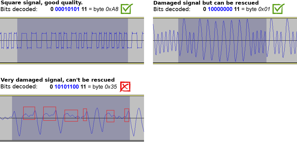
As you can see in the images, the data will be recoverable as long as the transition between pulses crosses the zero (horizontal line). Otherwise (as it appears at the red boxes) you would have to edit the waves by hand to fix them, which is a hard work and can be exasperating.
In order to see this type of graphics we recommend using some audio editing program such as Audacity (a free, open source, cross-platform audio software).
3. Steps to create a good conversion to TSX
Now we will go on to enumerate the steps and methods to get a correct and validated TSX as far as possible.
3.1. Digitize the tape to WAV format
The objective of this point is, from a tape, obtain a WAV file as correct as possible. This is: get defined square pulses and minimize the background noise.
To create the WAV from tape you can use the above mentioned Audacity program.
To get square pulses you need to disable any type of filter/preprocessing that the cassette player has, the sound driver of your PC, or the audio record program.
In order to minimize the background noise, it is necessary to find a balance with the reproduction volume of the cassette. You must find the point where the signal is high enough so that the pulses are well defined and their transitions cross the center line of the zero, but low enough so that the signal does not saturate or increase the tape noise too much. This is mostly seen in the silences between data blocks.
If by deterioration of the tape or action of a filter a sinusoidal signal is obtained, the data can still be readable if the wave correctly crosses the central line in each transition.
3.2. Using the makeTSX program
The basic use of the makeTSX program to convert a WAV to TSX is as follows:
makeTSX -wav Filename.wav -tsx Filename.tsx
There are other parameters that will be useful for controlling errors such as -v that will inform us for each bit and byte of everything that is found in the WAV file.
For more information about all of them you can run makeTSX without parameters and you will get a complete help list.
3.3. Error control
When extracting MSX blocks, a predictive error control system is used. This means that when we encounter a series of pulses that can not be identified as zeros or ones, we use the control bits (start / stop bits) of current byte and following ones to try to determine the correct value of that bit.
This feature is used by default but can be disabled with -di.
Unfortunately, it is not always possible to determine the correct value of this faulty bit, so in this situation makeTSX will ask us for the action to be taken, choosing between adding a bit #0 or #1.
In the blocks Spectrum (#10 and #11) the control of errors is something more complex since the control bits do not exist, however usually they have a modulation of much more precise frequency. Reason why the check method the times of a complete cycle (2 pulses) to determine if we are facing a bit #0 or #1. You can also use as a check the last byte of the block that is the checksum of bytes block to know if the conversion was correct or not.
makeTSX is prepared to read Spectrum blocks only if they are standard #10. For non-standard Spectrum blocks or with some type of error not recognized by the program, it's recommended to use MAKETZX to extract those specific blocks and add them to the final TSX using the ZXBlockEditor utility. The MAKETZX program is specialized in Spectrum blocks extraction, so it will do it much more reliably in case of signal problems.
3.4. Manual signal restoration
It's possible to edit the WAV watching the millisecond where the errors occurred (indicated at the conversion output using -v) and see if a damaged pulses restoration is posible to rescue them. We will use the Audacity program mentioned above and using the Edit icon:
At next image we can see a signal with a damaged wave and later corrected to a square shape so that's easily recognizable by makeTSX.
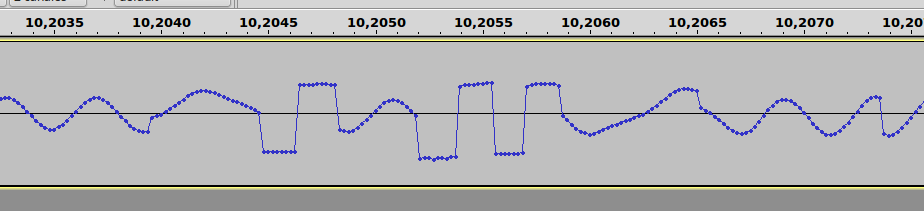
3.5. Data verification
Once we obtain a TSX file without errors being detected, we have to pass to its validation, since having obtained the file does not mean 100% that it is reliable.
The best option would be to have several WAVs of different tapes for each game to convert, but that can be quite complicated to achieve, so we use indirect verification methods.
3.5.1. Verification of tapes with MSX blocks
For games in which all data blocks are MSX without protections, the verification method to use is comparing them with the data of its corresponding CAS file (if previously preserved). To do this we will convert the CAS file to TSX using the cas2tsx.php script, and then open both files (our TSX and the converted CAS) with ZXBlockEditor and compare their block CRC one by one to detect differences.
If everything matches, it will be a great indication that we have a correct conversion to 99%.
If in any block the CRC do not match we will have to look at which byte/bytes are the differences, to do that we need to export both blocks with ZXBlockEditor (right mouse click -> Export as... -> Binary file *.bin) and use some program like vbindiff, that is a good choice of multiplatform command line binary comparer.
Suppose that the byte that differs is at 0x0217 offset of second block. Then we go to the makeTSX again and with the option -v we navigate de output and look for the millisecond where that byte is found in the WAV.
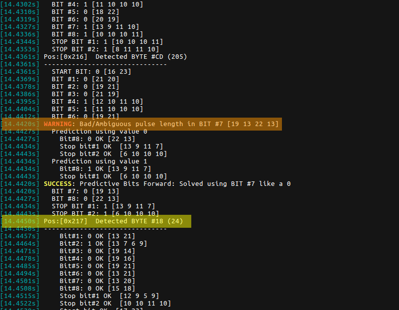
We can see below that a strange pulse has been detected at bit no.7, so we will have to open the WAV with Audacity and do zoom at second 14.4420.
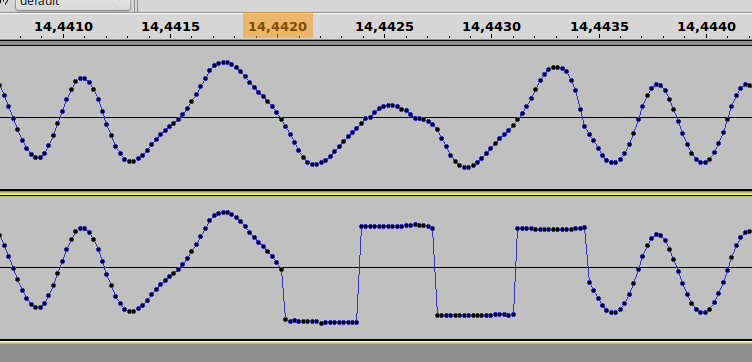
Here we can see the original signal above and the manually corrected below where we have corrected bits no.7 and 8.
The important thing to remember is that in case of any discrepancy between the CAS and the TSX, the best is go to the original source, the WAV, and so be able/try to determine the correct value of those bits.
3.5.2. Verification of tapes with Spectrum blocks
Everything indicated in previous section is valid for the MSX blocks of these tapes, except that at least one of the #4B blocks there will be a group of bytes that will be different to their respective in CAS block. This is due to the Spectrum blocks load routine (patched in the CAS to read only MSX blocks). In this case, if the TSX load is checked correctly we could assume the Spectrum load routine as correct.
In the Spectrum blocks (with ID #10 and #11) you can easily check if the checksum is correct or not, even so, you can also compare their CRCs with their respective CAS blocks even if they have different formats, just export the blocks to files and take care if flag (first block byte) and checksum (last one) are present in both files before compare them.
Be careful also with zeros at end of CAS block due a CAS format limitation: all blocks must have a byte length multiple of 8 so blocks are zero filled if needed. You need to remove them for CRCs comparation.
The goal is therefore to obtain two blocks of same size, starting and finishing with the same bytes, only then we can compare their CRCs.
It is important to always remember that if we doubt about the verification of Spectrum blocks we can always use MAKETZX as indicated in chapter 3.3 and add those problematic blocks by editing your TSX.