Intro_Course_4_4 - nasa/gunns GitHub Wiki
This introductory course can’t teach everything there is to know about designing networks, but here are a few important principles to always follow:
When it comes to the computational demand of a network, links are cheap and nodes are expensive. As much as possible, avoid having excess nodes that aren’t needed. If you can solve a problem with links instead of nodes, use the links. One good way to reduce nodes is to:
If you have a flow path with 2 or more conductors in series, you can combine the resistive effect of the 2 conductors into one conductor and eliminate the node in between them. For instance, you might start with a fan with an upstream filter, like so:
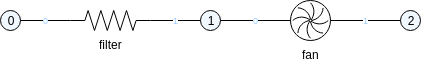
Instead, you can just use the fan by itself, and reduce its conductance to account for the resistance of the filter:

- Always use the simplest link that does the job you need. A good rule of thumb is to go with the most base class in the link class hierarchy that does the job.
- The link help pages describe what the links do, which class they extend, and how to use them. Consult these to decide which link best suits your needs.
It is a good idea to use a consistent naming scheme for the objects in your networks, especially the Links. Links are the main models of the vehicle hardware you are simulating; your customers may be looking for certain names. You might use hardware part numbers or designation codes, or more descriptive names; either way, using consistent naming patterns and capitalization will help you and your users find these objects in Trick View for maintenance, debug, and so forth. Consider how the customer might prefer the names to appear.
Along the same lines as naming convention, put some effort into making the drawing visually presentable. Draw.io can be used to easily view the drawing or export an image of the drawing along with the code; this serves as documentation of the layout and make-up of your network. This can be valuable to you and your users as a quick reference. A jumbled spaghetti ball of criss-crossing connection lines, sloppy shape sizing and arrangement, etc. not only makes it hard to use as a reference, but also reflects poorly on the model in the mind of the customer.
Some suggestions:
- Use colors & line patterns to distinguish different subsystems, circuits, fluid types, and so forth in your drawing.
- Annotate your drawing with important notes in text boxes.
- Use consistent shape sizes. Our default link shapes aren’t always consistent — you can resize them as needed to tidy things up.
- Resize the node shapes just small enough to contain their number to avoid wasting space and drawing too much attention to them.
- Try to match the layout of any vendor-supplied susbsystem diagrams that you may have referenced in the network design. Since your customer might use the same diagrams as a reference, this makes it easy for them to understand your model in context of the actual vehicle.