GunnsThermoelectricDevice - nasa/gunns GitHub Wiki

This link extends GunnsBasicConductor with a model of the Seebeck, Peltier and Thompson thermoelectric effects and Joule heating in a thermoelectric device (TED).
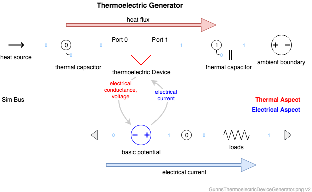
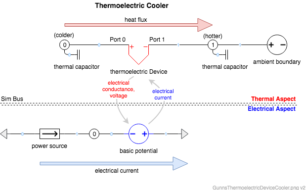
This models the thermal aspect of one TED in a thermal network, and the electrical aspect is a GunnsBasicPotential (voltage source + conductor) in an electrical network. We define one TED to be any number of thermocouples (p-n conductor pairs) that are thermally in parallel (i.e. share the same end plates) and electrically in series. This link can be configured to represent just one thermocouple, or multiple thermocouples (a "thermopile") in such an arrangement. The configuration data defining the thermoelectric properties of the thermocouples is flexible in scope: it can define a single p-type or n-type element that is then multiplied by 2 * the number of thermocouples in the TED, or it can define the overall properties of the entire TED. See configuration details below.
This link can model the thermal aspect of:
- Thermoelectric generators, such as a radioisotope thermoelectric generator (RTG).
- Thermoelectric coolers (heat pumps), such as used in refrigeration.
- Thermocouple temperature sensors.
- A temperature-sensitive resistor whose temperature and resistance change due to its waste heat. A classic example is an electric stove-top burner.
Assumptions & Limitations:
- If material properties are given for one p-type or n-type element (see below), then they are assumed the same for the other element type, with opposite polarity.
- This model does not ensure that overall efficiency < 1. That is left to the user's configuration data.
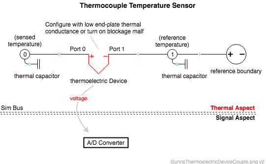
Port 0 is the positive terminal, and Port 1 is the negative terminal. Note that GunnsDraw doesn't force you to connect the Port 0 connector line to the side of the link shape marked '+', so you should flip or rotate the shape as needed to avoid confusion.
Below are example aspect diagrams of some of the model uses listed above. Here is a configuration to model a thermoelectric generator, such as an RTG:

Here is how to set up a thermoelectric cooler, such as in a refrigerator:

Here is how to model a thermocouple temperature sensor. Normally we don't model the voltage of the thermocouple itself, but simply send the "truth" temperature to a SensorAnalog model. However this is an example of when we want to actually model the thermocouple voltage to give to the vehicle's A/D converter or other signal handler. Note that in this case we don't want any thermal conductance to leak heat between the sensed temperature and the reference, so we'd configure the link to have none:

This link models one TED. Multiple TED's can be staged or cascaded together in real-world applications. In these cases, simply instantiate this utility separately for each stage, each with its own objects. Stages can be thermally in series (i.e. the "hot" plate of one TE stage is connected to the "cold" plate of the next) or thermally in parallel (both stages' "hot" plates connect to the same sink node, etc). In these cases, the stages can share the same thermal network node where they interface, but make sure to combine their thermal capacitance into just one thermal capacitor link on each node. The same goes for the electrical aspect staged in parallel or series.
Port Connection Rules (These are limitations on the port connection to nodes that the link enforces in run-time):
- Same as GunnsBasicConductor.
Other Rules (These are extra rules you should always try to follow):
- The Peltier and Joule heating effects add/remove heat directly to the attached nodes. Therefore, you should be careful about using this link with non-capacitive nodes and ensure there's always a place for heat to go to or come from in the network. For most applications it is recommended that both nodes be capacitive and have connections to other nodes in a thermal circuit. The only time you don't need node capacitance is when there will be no Peltier & Joule heating, either by giving zero Seebeck coefficients or not driving the input electrical current. The thermocouple temperature sensor example above is such a case.
Configuration Data Parameters:
- numThermocouples (default = 0, must >= 0.5): this tells the link how to scale the remaining material properties based on how many thermcouples are in this TED. If the material properties are given for the overall TED, then use 0.5 here. Else, this will be the number of thermocouples (p-n pairs) in the TED, which should be whole numbers >= 1.
- geometryFactor (default 0 (m), must > 0): If the material properties are given for the overall TED, then use 1.0 here. Else, this is the ratio of cross-sectional area to length of each p-type or n-type element.
- These terms define the material properties. You can either define these for the overall TED as a whole, or for a single p- or n-type element. Note that which way you define it affects how you should configure the other parameters -- see their descriptions.
- electricalResistivityCoeff0 (default = 0 ohm*m): 0th-order coefficient of a linear curve fit of the material electrical resistivity (ohm*m) as a function of temperature (K).
- electricalResistivityCoeff1 (default = 0 ohm*m/K): 1st-order coefficient of a linear curve fit of the material electrical resistivity (ohm*m) as a function of temperature (K).
- seebeckCoeff0 (default = 0 v/K): 0th-order coefficient of a 2nd-order polynomial curve fit of the material Seebeck effect (v/K) as a function of temperature (K).
- seebeckCoeff1 (default = 0 v/K2): 1st-order coefficient of a 2nd-order polynomial curve fit of the material Seebeck effect (v/K) as a function of temperature (K).
- seebeckCoeff2 (default = 0 v/K3): 2nd-order coefficient of a 2nd-order polynomial curve fit of the material Seebeck effect (v/K) as a function of temperature (K).
- thermalConductivityCoeff0 (default = 0 W/m/K): 0th-order coefficient of a 2nd-order polynomial curve fit of the material thermal conductivity (W/m/K) as a function of temperature (K).
- thermalConductivityCoeff1 (default = 0 W/m/K2): 1st-order coefficient of a 2nd-order polynomial curve fit of the material thermal conductivity (W/m/K) as a function of temperature (K).
- thermalConductivityCoeff2 (default = 0 W/m/K3): 2nd-order coefficient of a 2nd-order polynomial curve fit of the material thermal conductivity (W/m/K) as a function of temperature (K).
- endPlateThermalConductance (default = 0 W/K, must >= 0): If the material properties are given for the overall TED and the thermal conductivity already includes the TED's end-plates, then use 0 here. Else, this is the thermal conductance of each end-plate.
- minTemperature (default 0 K, must > 0): This is the lower bound on temperature for the materials properties curve fits.
- maxTemperature (default 0 K, must > minTemperature): This is the upper bound on temperature for the materials properties curve fits. This mininum & maximum should bound the valid range of temperature for your curve fits. If the node temperatures are outside this range, the link uses these limits instead for the material properties.
Input Data Parameters:
- malfBlockageFlag: Same as GunnsBasicConductor.
- malfBlockageValue: Same as GunnsBasicConductor. This malfunction blocks the conductance of heat between the end-plates, so it effectively degrades the material thermal conductivity of the thermocouples.
- malfThermoelectricEffectsFlag (default = false): This is the initial state of the thermoelectric effects scale malfunction.
- malfThermoelectricEffectsSclar (default = 0, must >= 0): This is the initial value of the thermoelectric effects scale malfunction scale factor. When the malfunction is active, it scales the Seebeck coefficients of the thermocouple material, which then scales the Seebeck, Peltier & Thompson effects accordingly. So this can be used to either reduce (towards zero) or increase (>1) the amount of these effects.
- N/A
- N/A