GunnsFluidSublimator - nasa/gunns GitHub Wiki

This is the fluid aspect of a sublimator. The sublimator takes in liquid coolant from a feed source and exposes it to vacuum in a porous plate. The liquid begins to boil in the plate due to vacuum, and this pulls enough heat out of the liquid that the remaining liquid begins to freeze, creating an ice layer (called the ice pack) in the plate. Thereafter, the ice pack sublimates in the vacuum, providing a heat sink for attached heat exchangers. More feed coolant is pulled in to maintain the ice pack as it sublimates.
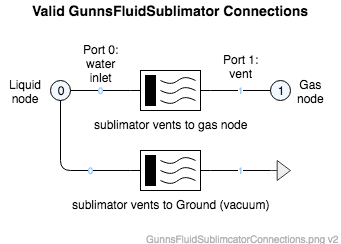
The inlet port of the link is always connected to a liquid node in the network. The exit port is connected to either a gas node or the Ground node. The sublimator link can model the effects of back-pressure in the vapor vent area - use a gas node connected to your system's vent region of the network in this case. If no modeling of back-pressure is needed, or you want a perfect vent, hook up the exit port to the Ground node. These options are shown below:
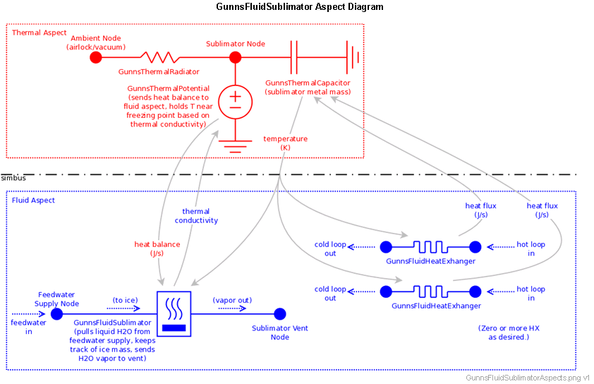
The aspect diagram below gives an example of how the sublimator link interfaces with other aspects for cooling a system. The sublimator controls the temperature of its thermal node via a potential source in the thermal network. The strength of that control is dependent on several factors, including the amount of ice in the sublimator's ice pack, etc. The thermal node receives heat flux from attached heat exchangers or other objects, and the resulting total heat balance is returned to the fluid sublimator link. This heat balance drives the rate of ice sublimation and demand rate on the feedwater supply.
Port Connection Rules (These are limitations on the port connection to nodes that the link enforces in run-time):
- Port 0 must connect to a non-Ground node containing liquid.
- Port 1 must connect to either the Ground node or a non-Ground node containing gas.
Other Rules (These are extra rules you should always try to follow):
- Currently, this model only works for water as the operating fluid. The liquid inlet node should contain GUNNS_WATER, and the network must, whether or not you use a gas exit node, also contain GUNNS_H2O as one of its constituents.
Configuration Data Parameters:
- gasType (default = FluidProperties::NO_FLUID, must equal a fluid constituent in the network): This is the fluid type of the sublimated vapor. Currently only water is supported as the operating fluid, so this should be GUNNS_H2O.
- heatOfVaporization (default = 0 kJ/kg, must be > 0): This is the heat of vaporization of the operating fluid. Since only water is supported, this should be 2257 kJ/kg.
- heatOfFusion (default = 0 kJ/kg, must be > 0 and < heatOfVaporization): This is the heat of fusion of the operating fluid. Since only water is supported, this should be 334 kJ/kg.
- triplePointTemperature (default = 0 K, must be > 0): This is the triple-point temperature of the operating fluid. Since only water is supported, this should be 273.15 K.
- maxIceMass (default = 0 kg, must be > 0): This is the maximum mass of ice that is contained when the ice pack is full.
- iceCoverageFraction (default = 0, must be (0-1)): This is the faction of the maxIceMass at which the porous plate becomes completely covered with ice. When the ice mass is below this fraction, liquid breakthrough of the plate is possible.
- maxThermalConductivity (default = 0 W/K, must be > 0): This is the thermal conductivity value sent to the thermal potential link in the thermal network (see aspect diagram above) when the ice pack is 100% full, i.e. current ice mass = maxIceMass. This affects how much the thermal node temperature rises from the freezing point under heat load, and how much heat the sublimator pulls from the connected system. Higher values result in more heat sink. With a full ice pack, the heat flux the sublimator pulls from the thermal network is this value times temperature of the sublimator thermal node. This conductivity is scaled in runt-time by the fraction of ice pack currently filled.
- plateConductivity (default = 0 m2, must be > 0). This is the fluid conductivity of the porous ice-pack plate. When the plate is not completely covered and conditions do not allow sublimation, liquid leaks through the porous plate and floods the exit vent. This is called breakthrough. This value determines the flow rate of liquid breakthrough, and behaves just like the maxConductivity parameter of a GunnsFluidConductor. Note that since GUNNS does not allow 2 fluid phases in the same node, the leaked liquid is converted to an equal mass of vapor in the exit node.
- thermalConductivityGain (default = 0, must be (0-1)): This is the gain of a stability filter on the thermal conductivity sent to the thermal aspect. We recommend a value of 0.01.
Input Data Parameters:
- malfBlockageFlag (default = false): In this link, this malfunction plugs the porous plate, reducing the volume that can contain ice. This reduces the sublimator's ability to sink heat.
- malfBlockageValue: Same as GunnsFluidConductor.
- iceMass (default = 0 kg, must be >= 0): This is the initial mass of ice in the sublimator.
- structureTemperature (default = 0 K, must be >= 0): This sets the initial temperature of the sublimator structure. Recommend 273.15 K. When integrated with the thermal aspect as shown above, this value doesn't matter because it is overwritten by values from the thermal aspect.
- N/A
- N/A