GunnsFluidRegulatorValve - nasa/gunns GitHub Wiki

This link models a pressure regulator valve, which modulates its position to maintain a sensed control pressure above a crack pressure. This is a 4-port link:
- Port 0 - valve flow inlet, similar to a GunnsFluidValve.
- Port 1 - valve flow exit, similar to a GunnsFluidValve. Fluid flows through the valve between Ports 0 and 1, just like a normal GunnsFluidValve.
- Port 2 - sensed control pressure positive port.
- Port 3 - sensed control pressure negative port. The difference between the positive and negative ports is the sensed control pressure - this is the pressure the valve tries to regulate. By connecting these pressure ports to nodes, the valve can be configured to regulate between any two nodes in the network (including Ground).
Like GunnsFluidCheckValve, this is a pneumatically operated valve, meaning it updates its own valve position and does not require the position to be input from a controller model.
Although this link does not derive from GunnsFluidValve or GunnsFluidConductor, it has identical functionality as a GunnsFluidValve between ports 0 & 1. It has conductivity, expansion cooling, and heat convection with the wall. The link does not modify the mixture of the fluid passing through it.
Ports 0 and 1 of the GunnsFluidRegulatorValve can be hooked up to nodes in exactly the same way that regular fluid conductors can. Ports 2 & 3 can likewise be hooked up to any two nodes in the network (including Ground). As with the GunnsFluidCheckValve, we recommend placing a stability volume on either the inlet or exit nodes, preferably whichever one is being sensed via a pressure port. Note that in these illustrations, we use dashed lines connecting the control pressure ports for clarity -- but GunnsDraw doesn't care what line formatting you use.
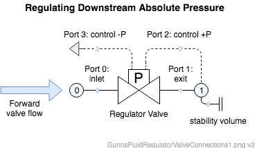
There are many ways to hook up a regulator, some of which are shown here. These first two examples are the most commonly used, where the valve is used to regulate its dowstream pressure. Hooking the positive pressure (Port 2) to the downstream flow node and the negative (Port 3) to Ground causes the control pressure to always equal the absolute pressure of the downstream node, and thus the downstream node's absolute pressure is regulated:
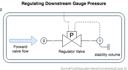
Likewise, hooking up the negative pressure port to the ambient node (shown here as Node 2) causes the control pressure to be the gauge pressure between the downstream flow node and the ambient:
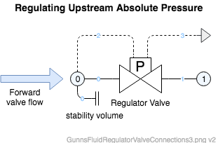
The regulator can be used to sense and respond to any two pressures in the network, and sometimes it is useful to have it respond to pressures other than the downstream node. Regulating the upstream node absolute pressure would look like this:
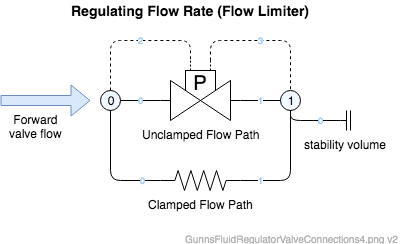
The regulator can even act like a flow limiter, which clamps closed in response to excessive flow rate. Since flow rate through a conductor is proportional to delta-pressure, tuning the regulator to respond to its own pressure drop causes it to close under high flow rate and re-open when flow drops to a desired amount. The regulator valve closes fully, so placing another conductor link in parallel models the smaller but non-zero clamped conductivity of the real limiter. Note that when the regulator closes under high flow rate, the pressure drop actually increases further even though the flow rate has dropped to zero (plus the clamped flow rate thru the parallel smaller conductance, which creates the larger pressure drop across the same two nodes). Thus the valve stays closed until the flow rate through the clamped flow path is reduced enough such that its pressure drop falls below the regulator's reseat pressure. In this configuration the regulator's crack, reseat & full-open pressures can be set very close to each other so it snaps fully open/closed in one pass, with little risk of the valve chatter problem discussed below.
Port Connection Rules (These are limitations on the port connection to nodes that the link enforces in run-time):
- Ports 0 and 1 (the flow ports) cannot connect to the same non-Ground node.
- Ports 2 and 3 (the control pressure ports) cannot connect to the same non-Ground node.
Other Rules (These are extra rules you should always try to follow):
- Same as GunnsFluidConductor.
Configuration Data Parameters:
- maxConductivity: Same as GunnsFluidConductor.
- expansionScaleFactor: Same as GunnsFluidConductor.
- rateLimit: Same as GunnsFluidCheckValve.
- thermalLength: Same as GunnsFluidValve.
- thermalDiameter: Same as GunnsFluidValve.
- surfaceRoughness: Same as GunnsFluidValve.
- reseatPressure (default = 0.0 (kPa, must be > crackPressure)): This is the control pressure at and above which the valve will move to fully closed.
- crackPressure (default = 0.0 (kPa, must be > fullOpenPressure)): This is the control pressure at and below which the valve will begin to open.
- fullOpenPressure (default = 0.0 (kPa)): This is the control pressure at and below which the valve will move to fully open.
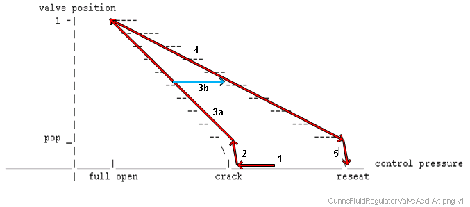
- popPosition (default = 0.0, must be [0-1]): This is the pop position shown in the above valve position chart. It must be between 0 and 1, non-inclusive. At positions below the pop position, the valve moves more rapidly between the pop position and fully closed, based on the popSlopeScale. In the case where popSlopeScale = 1.0, the pop segment slopes are the same as the slopes between pop and full-open, so "pop" is effectively removed from the valve and this pop position value doesn't matter.
- popSlopeScale (default = 0.0, must be >= 1): "Pop" models the tendency of valves to initially jump open due to internal friction in the valve mechanism. This is an optional effect, and if not needed, we recommend turning off the effect by setting this value to 1. Otherwise, this value is the ratio of the pop segment slopes to the normal segment slopes in the valve position chart above. The higher the value, the more rapidly the valve will move when popping (note that the rateLimit always still applies). When desired, we typically use a value between 1 and 10.
- inletDependencyCoeff0 (default = 0.0): This term, along with inletDependencyCoeff1, configures the optional effect of the regulated pressure being biased in response to the inlet pressure. This is commonly called the 'Inlet Dependency Effect' or 'Supply Pressure Effect'. This terms defines the 0th-order coefficient, or the intercept, of the line equation for the model of bias to the regulated pressure as a linear function of the inlet (Port 0) pressure. Leaving these terms zero creates zero bias.
- inletDependencyCoeff1 (default = 0.0): This term, along with inletDependencyCoeff0, configures the optional effect of the regulated pressure being biased in response to the inlet pressure. This is commonly called the 'Inlet Dependency Effect' or 'Supply Pressure Effect'. This terms defines the 1st-order coefficient, or the slope, of the line equation for the model of bias to the regulated pressure as a linear function of the inlet (Port 0) pressure. Leaving these terms zero creates zero bias. Real-world regulator valves commonly see their regulated pressure decrease in response to increasing inlet pressure (a negative value for this slope term), but this model allows you to define the bias to go in either direction relative to changing inlet pressure. Note: you should take care to avoid excessively large values in this term, as that can create too much sensitivity between the inlet and regulated pressures and lead to valve chatter and control instability.
Input Data Parameters:
- malfBlockageFlag: Same as GunnsFluidValve.
- malfBlockageValue: Same as GunnsFluidValve.
- position: Same as GunnsFluidValve.
- malfLeakThruFlag: Same as GunnsFluidValve.
- malfLeakThruValue: Same as GunnsFluidValve.
- malfPressureBiasFlag (default = false): Initial state of the control pressure bias malfunction flag.
- malfPressureBiasValue (default = 0.0 (kPa)): Initial state of the control pressure bias malfunction value. This value adds to the valve's control pressure, so a positive malfunction value causes the valve to control a lower pressure.
- setPointPressureBias (default = 0.0 (kPa)): This is an additional nominal bias to the control pressure. However unlike the malfPressureBiasValue, this value subtracts from the valve's control pressure, so a positive bias causes the valve to control a higher pressure.
- wallTemperature: Same as GunnsFluidValve.
- malfPreviousFlag (malfStuckFlag): Same as GunnsFluidCheckValve.
- malfCurrentFlag (malfFailToFlag): Same as GunnsFluidCheckValve.
- malfCurrentValue (malfFailToValue): Same as GunnsFluidCheckValve.
-
Valve Chatter: First read up on the same problem in GunnsFluidCheckValve
as the same concepts apply. The differences are:
- Terminology between "open" and "crack" pressures, etc. "Open" pressure from the check valve corresponds to the regulator's fullOpenPressure, and "Close" pressure from the check valve corresponds to the regulator's reseatPressure.
- Stability volume should always be added to the flow nodes if their pressures are being sensed by the regulator's control pressure ports. In most configurations the regulator senses the downstream node, so in those cases that node should have some capacitance. In the case where both flow nodes are being sensed (such as in the "check-valve" case shown above), just adding volume to the downstream node is usually sufficient for stability.
-
Pressure Overshoot: This happens when the control pressure is increasing and overshoots
the reseat pressure before the valve can fully close. Common fixes are:
- Increasing the downstream system volume and decreasing the valve's flow rate relative to each other. When the flow through the valve is very high compared to the downstream volume the valve is filling, the downstream pressure can refill too quickly and overshoot the reseat pressure before the valve has time to close. Insufficient downstream (stability) volume and overly high valve flow rates also lead to the valve chatter problem, so it is a good idea to ensure both parameters are tuned properly to avoid both of these problems.
- Increasing the regulator's rateLimit. Too low of a rate limit causes the valve position to lag behind the position vs. control pressure slope and it reaches fully closed too late after the control pressure has passed the reseat pressure. Since this term can also sometimes cause valve chatter if set too high, there is sometimes a trade-off between valve stability and response time.
- N/A