GunnsFluidFlowController - nasa/gunns GitHub Wiki

This link extends the GunnsFluidConductor link with the ability to control a constant mass flow rate through the conductor. Refer to the flow equation in GunnsFluidConductor. This link modulates its effective conductivity G to control flow rate w to match the desired value. As the delta-pressure dp drops, the link increases G to maintain the constant w, and so on. This can be used to model a Flow Control Valve and similar devices.
The link is configured with a maximum conductance that the device can reach, corresponding to the fully open flow area of the flow control valve. This helps network stability and avoids dividing by zero when the delta-pressure is very small. The link also has a built-in proportional gain filter on G that can be tuned as needed to reduce oscillation and noise in the flow when in series with other dynamic links, like pressure regulators and so on.
The link has options for how it handles flow in the reverse direction. It can be configured to either control or block reverse flow. This is described in more detail below.
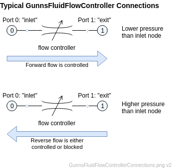
This link has the same connection rules as GunnsFluidConductor. The picture below shows how it is typically used:
Port Connection Rules (These are limitations on the port connection to nodes that the link enforces in run-time):
- Same as GunnsBasicConductor.
Other Rules (These are extra rules you should always try to follow):
- Same as GunnsBasicConductor.
Configuration Data Parameters:
- maxConductivity: Same as GunnsFluidConductor. This sets the maximum conductance the link can reach when it is controlling flow rate. For a flow control valve, this would correspond to the maximum throat area of the fully-opened valve.
- expansionScaleFactor: Same as GunnsFluidConductor.
- filterProportionalGain (default = 0.0, must be (0-1)): This sets the proportional gain of the stability filter in the link. A higher value allows the link control to the desired flow rate faster, but damps oscillations in the controlled rate less. A lower value causes more sluggish control but damps oscillations better. It is best to try a value of 1.0 and then lower it as needed to damp out oscillations if they occur.
- enableReverseControl (default = false): This sets whether the link controls (true) or blocks (false) flow in the reverse direction. As with all conductors, flow can only go from higher to lower potential. As shown in the diagram above, forward flow is defined in the direction from the link's Port 0 ("inlet") to Port 1 ("exit"). Forward flow is always controlled as described above. For reverse flow, the link can be configured to either control it in the same manner as forward flow, or to block it altogether. Bocking reverse flow would be equivalent to placing a check valve in the forward direction, so this saves you from having to add a separate check valve link in series.
Input Data Parameters:
- malfBlockageFlag: Same as GunnsFluidConductor. This malfunction combines with the flow rate override malfunction described below, and further reduces the actual flow rate through the link.
- malfBlockageValue: Same as GunnsFluidConductor.
- malfFlowRateFlag (default = false): This sets the initial active (true) or inactive (false) state of the link's flow rate override malfunction. When active, the link controls to the malfunction rate value instead of the normal rate command input.
- malfFlowRateValue (default = 0.0 (kg/s)): This initializes the flow rate value for the malfunction.
- flowRateCommand (default = 0.0 (kg/s)): This initializes the desired flow rate value for link to control to. Positive or negative value can be given, but the link always uses its absolute value and flow can only go in the direction from higher to lower potential.
- N/A
- N/A